High Magnetic Field Assisted Pulsed Laser Deposition System

a laser deposition system and high magnetic field technology, applied in the field of thin film material preparation technology, can solve the problems of weak strength of magnet, inability to change the strength of one using the foregoing method, and rapid attenuation of the energy of reflected light, etc., to achieve low manufacturing cost, simple assemble and operation, and rational structure

Inactive Publication Date: 2016-11-24
HEFEI INSTITUTES OF PHYSICAL SCIENCE - CHINESE ACAD OF SCI
View PDF2 Cites 6 Cited by
  • Summary
  • Abstract
  • Description
  • Claims
  • Application Information

AI Technical Summary

Benefits of technology

[0016]As shown in the above-mentioned technical plan, the invention provides High Magnetic Field Assisted PLD System. A type of high magnetic field assisted PLD growth system may be achieved if the high magnetic field is introduced in-situ during the preparation of PLD thin film. Because of the design of combined assembly (sealed laser leading-in chamber and slide rail), vacuum-sealed video leading-in chamber and rotatable laser heating substrate table, etc., the advantages of the system compromises low manufacturing cost, rational structure, simple assemble and operation, stable and reliable service, etc. The system may be used in PLD thin-film in-situ growth and post-annealing thermal treatment, and to regulate the material microstructure and physical property. The invention plays an important role in material science, condensed matter physics research and new material exploration.
[0017]As for the invention, a raised vacuum chamber is stretched into the electromagnetic field and higher magnetic field strength cannot achieve limitations by vacuum chamber and electromagnetic space. Because the field direction is vertical to the transmitting direction of excited plasma (transverse magnetic field), the charged particles will deviate from original transmitting direction under the effect of Lorentz Force and go against thin-film growth. Therefore, the device may be used in post-annealing treatment in downfield after thin-film deposition rather than thin-film in-situ growth in magnetic field.

Problems solved by technology

The magnet provides a fixed magnetic field with weak strength (1 t) and is not suitable for high temperature.
However, one using the foregoing method cannot change the strength because of weak strength and limitations by a transverse magnetic field.
If a chamber mirror is used, the mirror is easily polluted within the chamber, thus the energy of reflected light will be attenuated rapidly.
Under high laser irradiation the polluted mirror is easily damaged, thus the design is unable to keep stable and work normally.
In addition, due to fixed substrate heating table, the angle between heating table (substrate surface) and magnetic field cannot be changed, so it is unable to regulate the microstructure of thin-film growth in different magnetic fields.

Method used


Image

  • High Magnetic Field Assisted Pulsed Laser Deposition System
  • High Magnetic Field Assisted Pulsed Laser Deposition System
  • High Magnetic Field Assisted Pulsed Laser Deposition System

Examples


specific embodiment 1

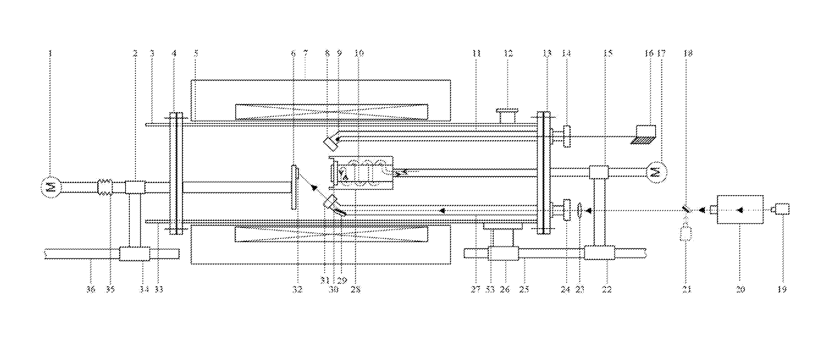
[0041]As shown in FIG. 1, the system is composed of superconducting magnet 7, pulsed laser 20, PLD cylindrical vacuum chamber, high vacuum unit (not shown), gas flow connected by vacuum seal with flange plate on both ends. It is composed of three parts:

[0042]double-layer clip-sheath cylindrical chamber used as water cooling 5, flange plate of heating table with substrate and rotating mechanism 13, and flange plate with target components and moving / rotating mechanism 4. The three parts are respectively fixed on sliding block 26, 22, and 34 used as water cooling 5, flange plate of heating table with substrate and rotating mechanism 4. The three parts are respectively fixed on sliding block 26, 22 and 34 using holder 53, 15, and 2. Sliding block 26 and 22 are installed on guide rail 25 and sliding block 24 is installed on guide rail 36. Two groups of guide rail are installed on optical table (not shown). The three parts may move one-dimensionally on the guide rail, which may be dismant...

specific embodiment

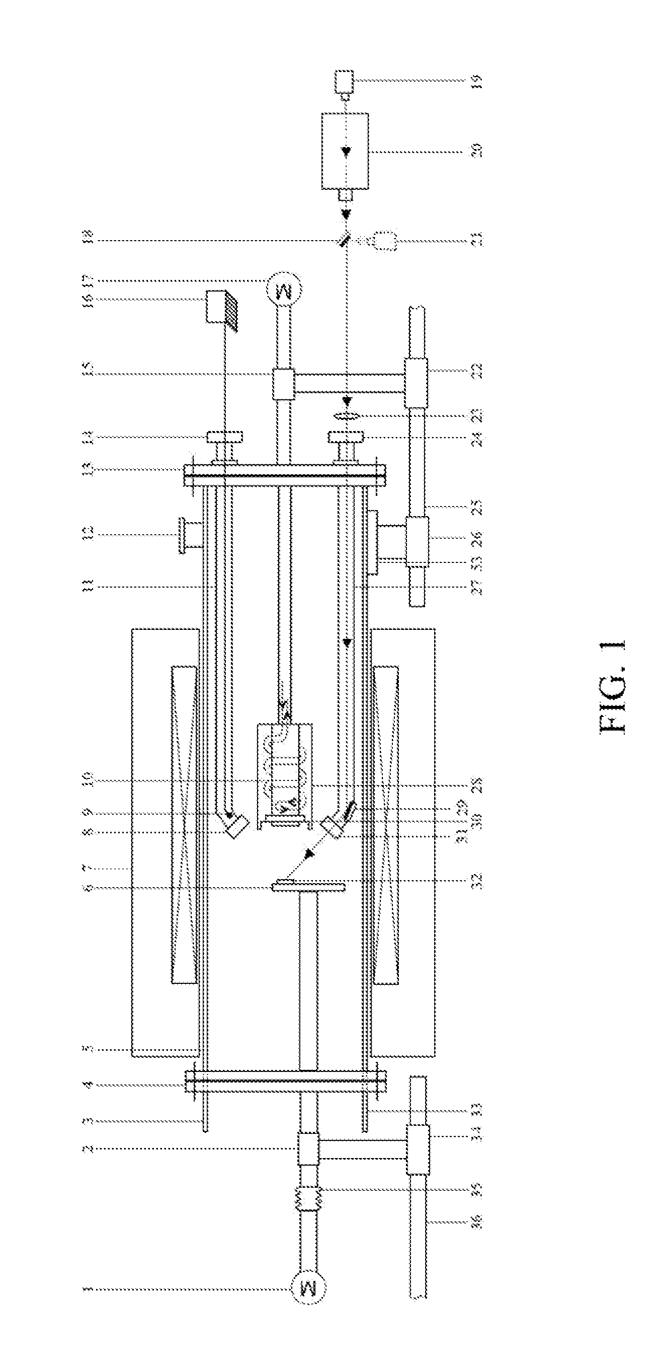
[0049]In order to change the angle between magnetic field and heating table (substrate surface of growth thin film), achieve film growth and post-annealing treatment under different magnetic fields orientation, so that thin-film growth microstructure and physical property can be regulated and controlled by magnetic field, it is necessary to design a flexible heating device. FIG. 2 gives the design plan of laser heating table. Change the flange plate 13 with substrate heating table and rotating mechanism as shown in FIG. 1 to flange plate 44 with laser heating table 38 in FIG. 2. It may achieve high magnetic field direction and higher temperature. Sealed laser leading-in chamber 50 and vacuum-sealed video-unit leading-in chamber 40 are installed on flange plate 44 in FIG. 2 are the same as relevant part 27 and 11 in FIG. 1. Similar to the assembly structure of flange plate 13 in FIG. 1, using the holder and sliding block 45, the flange plate 44 is installed on guide rail and slides, ...

specific embodiment iii

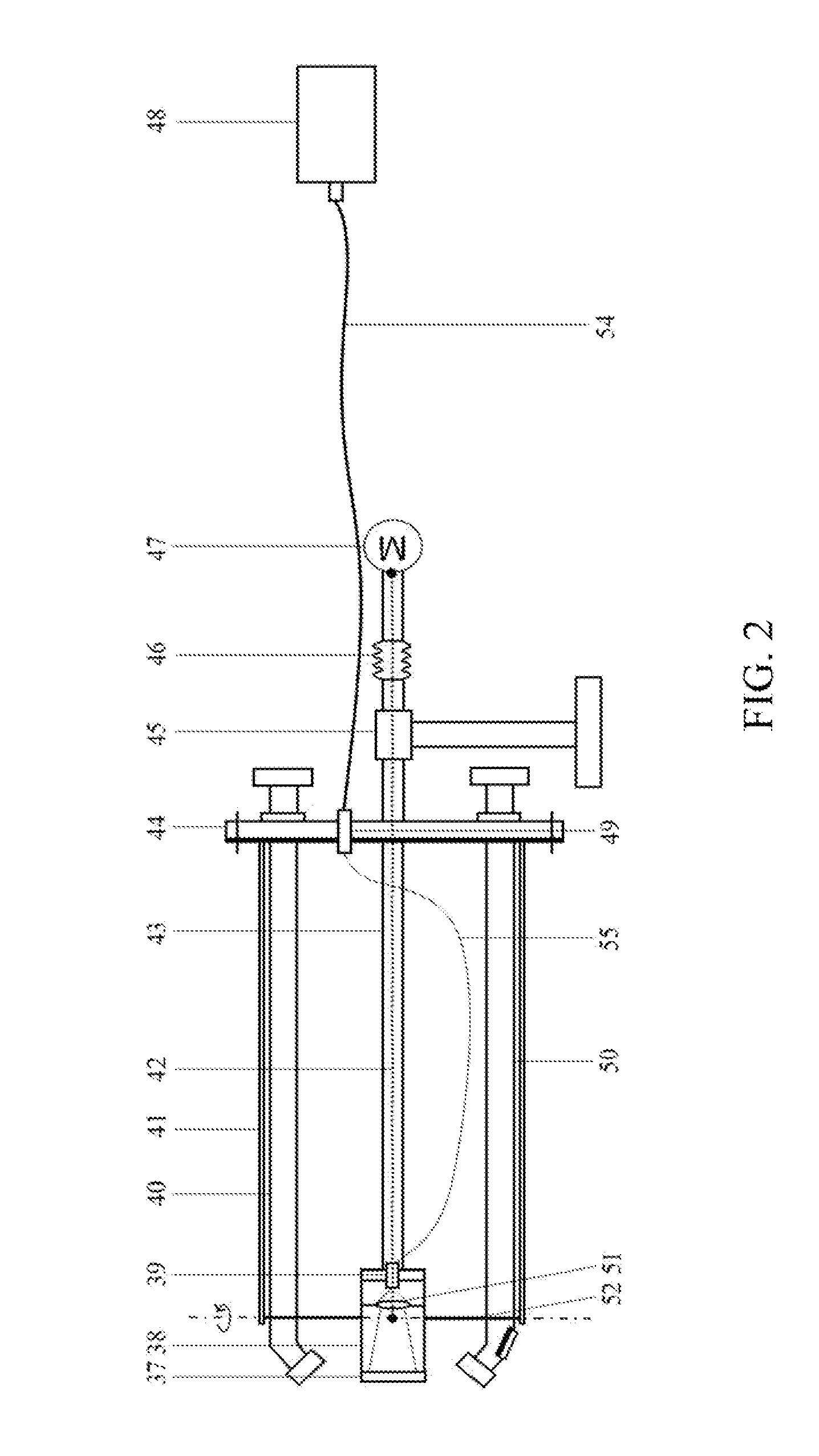
[0050]If the superconducting magnet has a small bore hole (or distance between magnetic field enter and port) and a large aperture, the PLD cylindrical vacuum chamber may be designed as the structure in FIG. 3. Differently from FIG. 1, an inclined laser leading-in chamber 27 is installed on the side pore of double-layer clip-sheath cylindrical chamber 5 rather than installing sealed laser leading-in chamber 27 on flange plate 13. A vacuum-sealed incoming-light quartz glass window 24 is installed on laser leading-in chamber 27. The laser leading-in chamber 27 is designed in an inclined angle to prevent the pulsed laser in target material 32 from blocking by the substrate heating table. The inclined angle (angle between the laser leading-in chamber 27 and chamber surface of double-layer clip sheath cylindrical chamber 5) is 30°-50°. When the system is working, a part of double-layer clip sheath cylindrical chamber 5 is placed into bore hole of superconducting magnet 7. The inclined la...


PUM

PropertyMeasurementUnit
focal lengthaaaaaaaaaa
reflection angleaaaaaaaaaa
wavelengthaaaaaaaaaa

Abstract

A type of High Magnetic Field Assisted PLD System consisting of pulsed laser and PLD cylindrical vacuum chamber inclusive of double-layer clip-sheath cylindrical chamber with water cooling located in the bore hole of superconducting magnet is disclosed. A flange plate in one side of the double-layer clip sheath is equipped with substrate heating table or laser heating table and rotating mechanism; the flange plate in another side is equipped with target components and moving/rotating mechanism. Either the substrate heating table or laser heating table is located in the center area of magnetic field of the superconducting magnet. A PLD (pulsed laser deposition) cylindrical vacuum chamber is located in the slide rail. A sealed laser leading-in chamber and a vacuum-sealed video-unit leading-in chamber is installed on the flange plate in one side of double-layer clip sheath cylindrical chamber.

Description

[0001]This application is a national phase application of PCT / CN2014 / 007154 entitled “High Magnetic Field Assisted Pulse Laser Deposition System,” filed on May 9, 2014, which claims priority to Chinese patent application No. 201410033519.X entitled “high Magnetic Field Assisted PLD System,” filed on Jan. 23, 2014. The contents of the foregoing applications are incorporated herein by reference.FIELD OF THE INVENTION[0002]The field relates to thin-film material preparation technology and a particular type of High Magnetic Field Assisted (PLD) Pulse laser depositions system.BACKGROUND OF THE INVENTION[0003]At present, as an ideal and non-contacting outfield driving force, the magnetic field may improve activity of reactant, promote ionic diffusion and influence grain nucleation, growth, grain boundary migration and recrystallization, and even the magnetic field may change the electron spin and nuclear spin state of reactant, in order to induce, new chemical reaction process change pref...

Claims


Application Information

Patent Timeline
Patent Type & Authority Applications(United States)
IPC IPC(8): C23C14/28C23C14/58
CPCC23C14/5806C23C14/28
Inventor DAI, JIANMINGZHANG, KEJUNLIU, QINZHUANGSHENG, ZHIGAOZHU, XUEBINWU, WENBINSUN, YUPING
Owner HEFEI INSTITUTES OF PHYSICAL SCIENCE - CHINESE ACAD OF SCI
Why Eureka
Try Eureka