Method for Operating a Gas Engine

a gas engine and gas technology, applied in the direction of machines/engines, electric control, output power, etc., can solve the problems of increasing the knock resistance significant reduction of the efficiency of the gas engine, and reducing the temperature in the combustion chamber of the cylinder, so as to achieve effective and simple manner, reduce the level of pollutants in the exhaust gas of the gas engine, and high efficiency

Active Publication Date: 2016-12-22
MAN NUTZFAHRZEUGE AG
View PDF18 Cites 1 Cited by
  • Summary
  • Abstract
  • Description
  • Claims
  • Application Information

AI Technical Summary

Benefits of technology

[0008]It is therefore an object of the invention to provide a method for operating a gas engine, in particular a stationary gas engine, and an apparatus having a gas engine, in particular a stationary gas engine, by which the gas engine can be operated with a high efficiency and the level of pollutants contained in the exhaust gas of the gas engine can be lowered in an effective and simple manner.

Problems solved by technology

However, thermodynamic conditions dictate that a very lean mode of operation of the gas engine can result in a significant reduction in the efficiency of the gas engine.
However, feeding in ammonia in this way is an involved process because of the provision of additional injectors, additional tanks and metering control (including sensors) and is expensive particularly because of the continuous consumption of ammonia.
As a result, the charge in a cylinder of the gas engine is initially expanded, resulting in a decrease in the temperature in a combustion chamber of the cylinder.
A decrease in the temperature in the combustion chamber leads to a rise in the knock resistance of the gas engine.
This high boost pressure or positive scavenging gradient across the combustion chamber leads to an increase in the slip of unburnt hydrocarbons (CyHz) in gas engines with external mixture formation, as a result of which a large quantity of hydrocarbons (CyHz) is emitted by the gas engine.
However, reducing the valve overlap generally causes a drop in the efficiency of the gas engine.
Moreover, the use of an NH3-SCR catalyst to lower the level of nitrogen oxides (NOx) emitted by the combustion engine has the disadvantages already mentioned.

Method used


Image

  • Method for Operating a Gas Engine
  • Method for Operating a Gas Engine
  • Method for Operating a Gas Engine

Examples


first embodiment

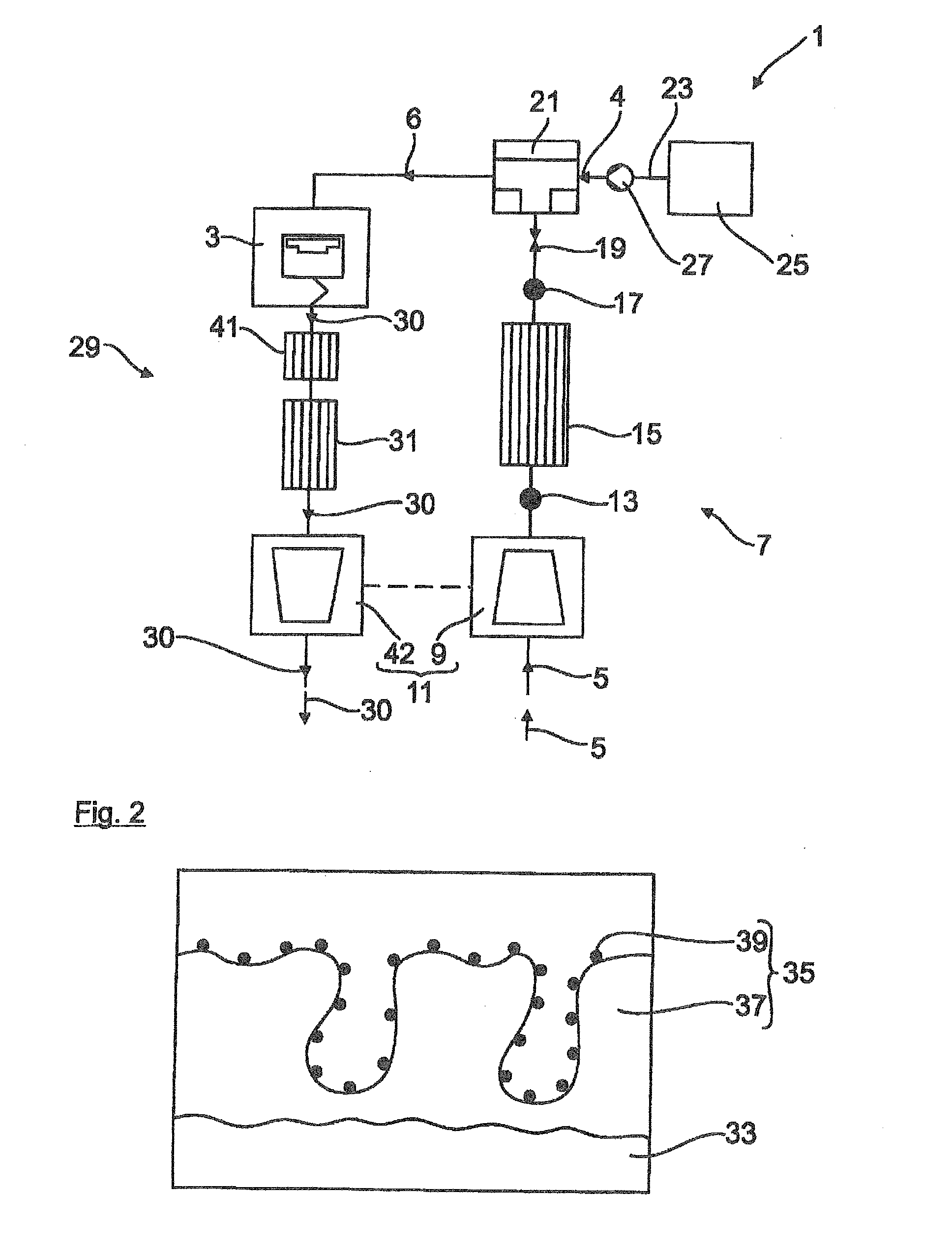
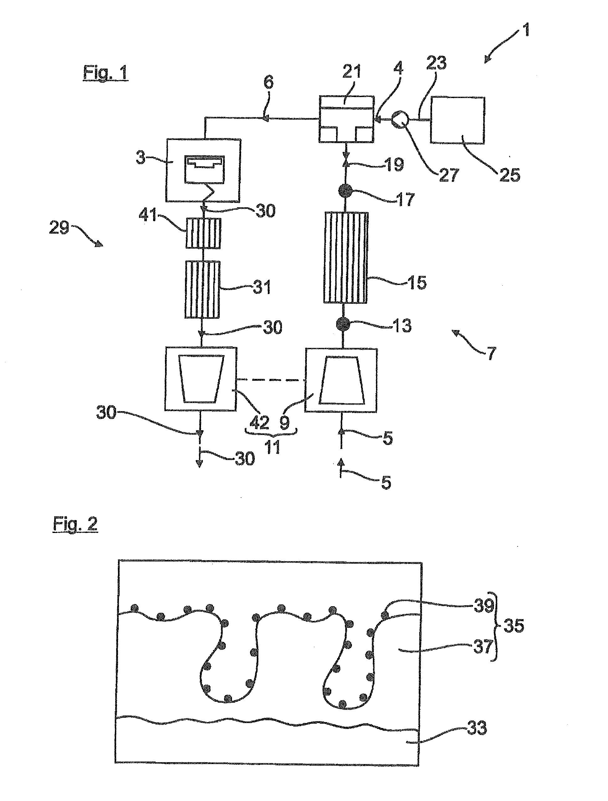
[0044]The construction of an apparatus according to the invention is shown in FIG. 1. The apparatus 1 has a gas engine 3, which is operated with a carbon-containing fuel gas 4 as fuel. The fuel gas 4 preferably has a methane content (CH4) greater than 80% and can be formed by natural gas, for example. The fuel gas / combustion air gas mixture 6 is here formed outside the gas engine 3 or externally, for example.

[0045]As is evident from FIG. 1, combustion air 5 flows into an intake tract 7 of the apparatus 1 during the operation of the gas engine 3. As viewed in the direction of flow of the combustion air, the intake tract 7 has a compressor 9 of an exhaust turbocharger 11, a pressure sensor 13, a charge air cooler 15, a pressure sensor 17, a throttle valve 19 and a fuel gas / combustion air mixing device 21. Here, by way of example, the fuel gas / combustion air mixing device 21 has connected to it a feed line 23, by which the fuel gas 4 stored in a fuel tank25 of the apparatus 1 is fed in...

second embodiment

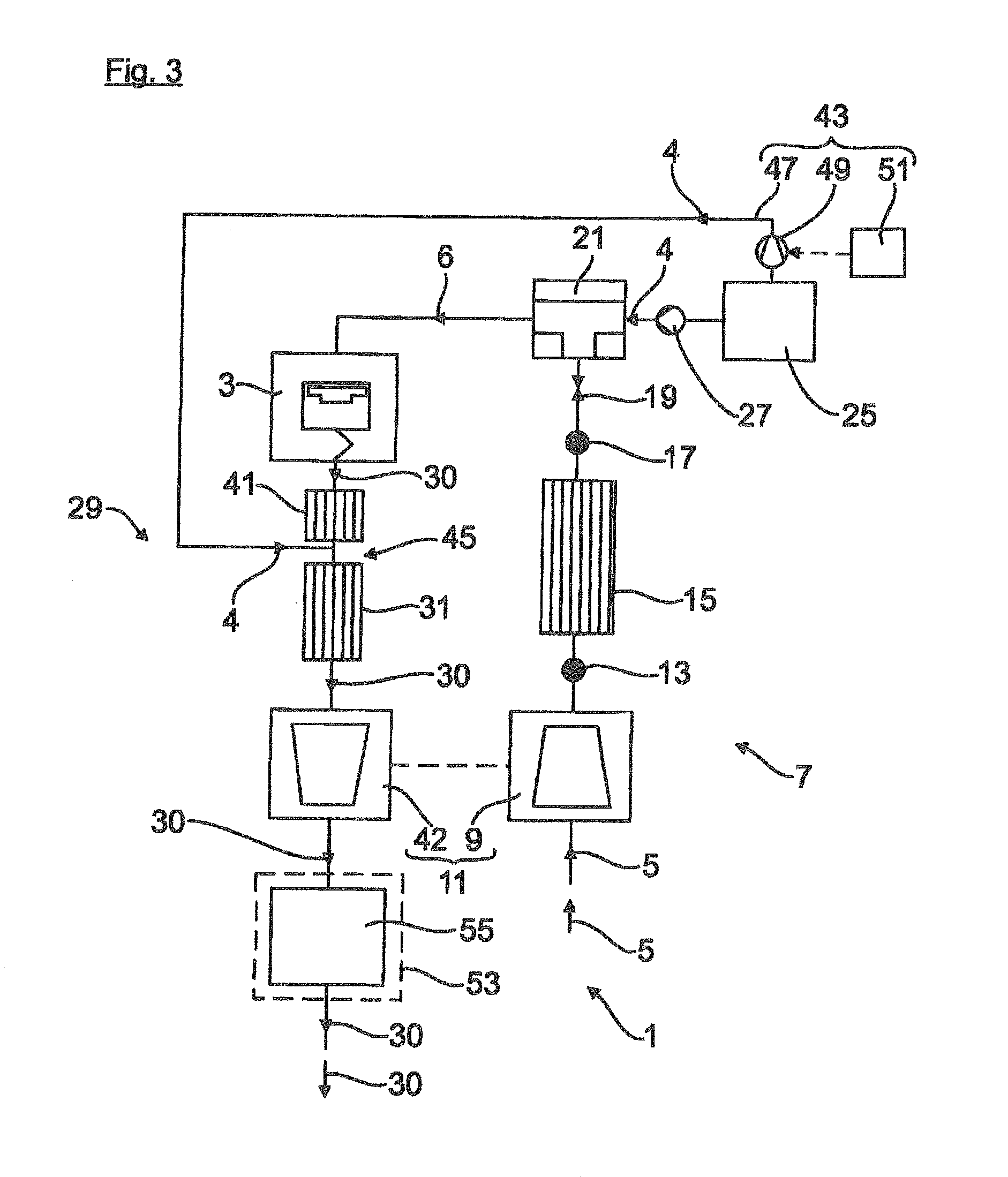
[0051]As is furthermore shown in FIG. 3, the apparatus 1 furthermore also has an energy recovery device 53, by which useful energy can be recovered or generated from the thermal energy of the exhaust gas 30. Here, the recovery of the energy can be accomplished by a cyclical thermodynamic process for example, e.g., by the Clausius-Rankine cycle. The energy recovery device 53 has a heat-absorbing heat exchanger 55, by which the thermal energy of the exhaust gas 30 is absorbed. Here, by way of example, the heat-absorbing heat exchanger 55 is arranged in or on the exhaust line 29 downstream of the exhaust turbine 42 of the exhaust turbocharger 11, as viewed in the direction of flow of the exhaust gas.

[0052]A third embodiment of the apparatus 1 is shown in FIG. 4. In comparison with the first embodiment shown in FIG. 1, the oxidation catalyst 41 is here arranged in or on the exhaust line 29 downstream of the SCR catalyst element 31, as viewed in the direction of flow of the exhaust gas.

[...


PUM


Abstract

A method for operating a gas engine having an adjoining exhaust line through which exhaust line exhaust gas of the engine flows includes: operating the gas engine in accordance with a Miller cycle, such that a closing point of at least one intake valve of the gas engine is in a crank angle range of from about 50° of crank angle before bottom dead center (BDC) to about 10° of crank angle before BDC; and lowering, by at least one selective catalytic reduction (SCR) catalyst element in the exhaust line, a level of nitrogen oxides (NOx) in the exhaust gas flowing through the SCR catalyst element using hydrocarbons (CyHz) as a reducing agent. At least some of the hydrocarbons (CyHz) flowing through the SCR catalyst element are constituents of the exhaust gas of the gas engine.

Description

BACKGROUND OF THE INVENTION[0001]1. Field of the Invention[0002]The invention relates to a method for operating a gas engine, in particular a stationary gas engine, to an apparatus having a gas engine, in particular a stationary gas engine, and to a vehicle, in particular a commercial vehicle, for carrying out the method and / or having the apparatus.[0003]2. Description of the Related Art[0004]The operation of a gas engine running on a carbon-containing fuel gas using a very lean fuel gas / air gas mixture (e.g., air / fuel ratio λ=1.7) is known. In this way, nitrogen oxides (NOx) emitted by the gas engine are kept low. However, thermodynamic conditions dictate that a very lean mode of operation of the gas engine can result in a significant reduction in the efficiency of the gas engine. Moreover, it may be necessary in the case of a gas engine operated on a lean mixture to provide a nitrogen-oxide-reducing exhaust gas aftertreatment in an exhaust line adjoining the gas engine, e.g., if t...

Claims


Application Information

Patent Timeline
Patent Type & Authority Applications(United States)
IPC IPC(8): F01N3/20
CPCF01N3/2066F01N3/28F02B43/02F02D43/00F02M21/0209F01N2570/14F01N2610/02F01N3/2073F01N2430/10F01N2590/08F01N2590/10F01N2610/03F01N2610/06F01N13/009F02D13/0269F02D19/02Y02A50/20Y02T10/12Y02T10/30
Inventor BARCIELA, BRUNOMCMACKIN, MARTIN
Owner MAN NUTZFAHRZEUGE AG
Why Eureka
Try Eureka