Piston ring and its production method

a technology of piston rings and internal combustion engines, which is applied in the direction of manufacturing tools, furnaces, heat treatment apparatus, etc., can solve the problems of poor thermal conductivity of silicon-chromium steel, low-alloy steel, and insufficient nitride, and achieve excellent thermal conductivity, efficient escape to the cylinder wall, and good workability

Active Publication Date: 2017-01-12
RIKEN CO LTD
View PDF4 Cites 3 Cited by
  • Summary
  • Abstract
  • Description
  • Claims
  • Application Information

AI Technical Summary

Benefits of technology

[0017]Because the total amount of alloy elements in low-alloy steel is limited to less than 3.0% by mass, the piston ring of the present invention has good workability and excellent thermal conductivity, making it possible for heat from a piston head to efficiently escape to a cylinder wall. With Si decreased in a matrix, part of C turned to carbide, and C segregated from grains to boundaries (boundaries of prior austenite grains), nitrogen (N) has a high diffusion coefficient in grains, increasing the depth of a nitrogen diffusion layer having predetermined hardness, thereby providing the nitrided layer with excellent wear resistance. Because nitriding is conducted at a temperature not so higher than the tempering temperature of a wire for the piston ring, the hardness of a base material is not excessively reduced by nitriding, enabling the piston ring to have a sufficient spring constant. The nitrided layer of the present invention can be applied to the side surfaces of a piston ring to have enough wear resistance, resulting in large economic and environmental contribution.

Problems solved by technology

However, because silicon-chromium steel, low-alloy steel, is not sufficiently nitrided, ion plating of chromium nitride (CrN) and chromium plating are used.
Though materials for the piston rings of JP 2000-282177 A and JP 2005-61389 A are categorized in low-alloy steel, the amount of alloy elements are slightly larger than those in so-called silicon-chromium steel, so that they are poorer than silicon-chromium steel in thermal conductivity.

Method used


Image

  • Piston ring and its production method

Examples


example 1 (

E1)

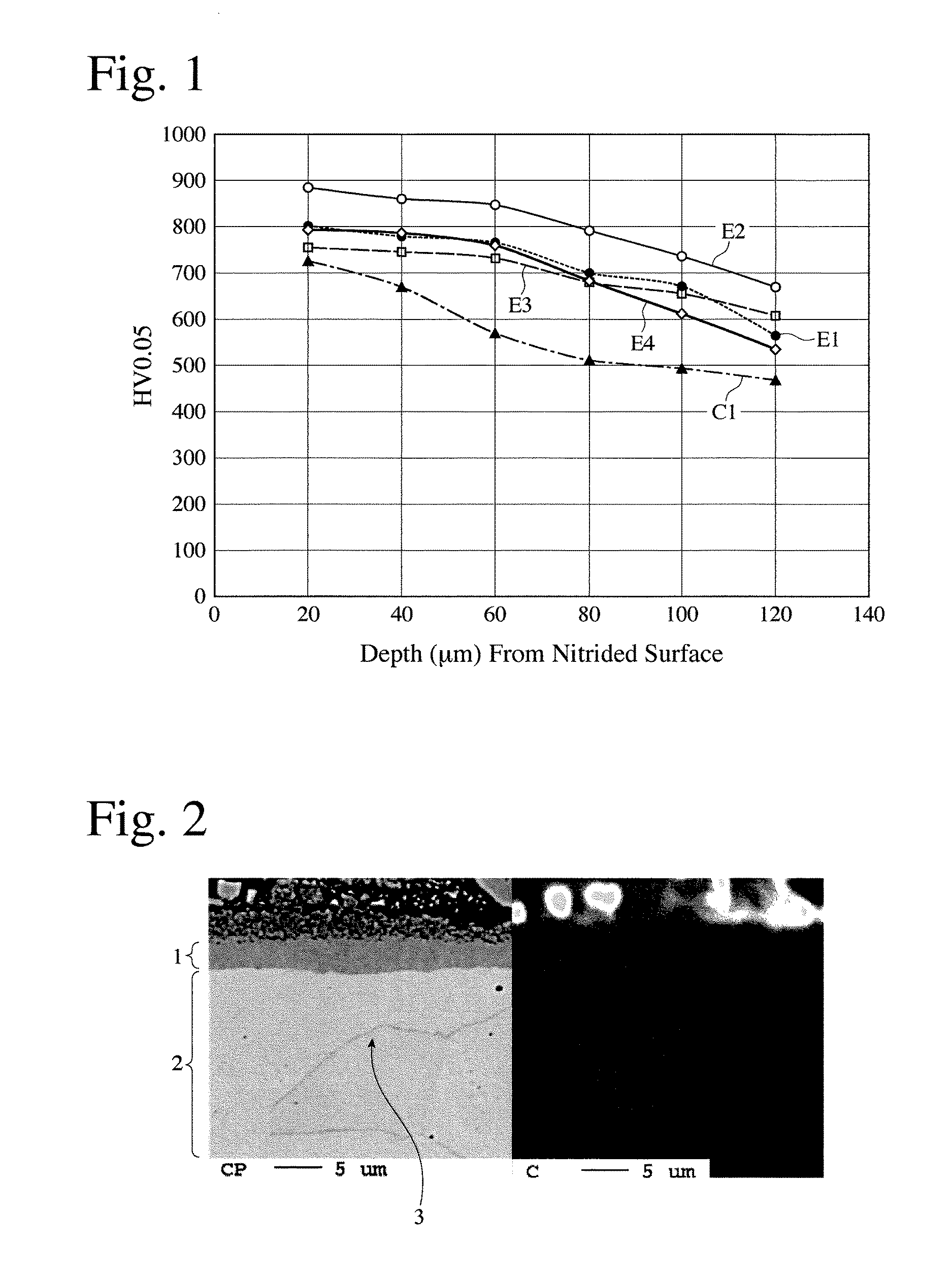
[0027]Steel having a composition comprising by mass 0.51% of C, 0.29% of Si, 0.72% of Mn, 0.92% of Cr, and 0.19% of V, the balance being Fe and inevitable impurities, was produced by melting in a 10-kg vacuum induction furnace. The steel was hot-rolled to form a rod having a diameter of 10 mm, and then drawn to form a wire having a rectangular cross section of 2.3 mm in thickness and 1.0 mm in width. Annealing was conducted at 700° C. for 60 minutes during the drawing step. Oil tempering was conducted by oil quenching from heating at 930° C. for 45 seconds to 60° C., and tempering at 470° C. for 60 seconds. The above wire was formed into a compression ring having a nominal diameter of 73 mm, which was subjected to a strain-removing heat treatment at 450° C. for 60 minutes, and provided with an ion-plated CrN coating on the outer peripheral surface, and a gas-nitrided layer on the side and inner peripheral surfaces. The nitriding conditions were 500° C. and 180 minutes. The hardne...

examples 2-4 (

E2-E4), and Comparative Example 1 (C1)

[0032]Each wire was produced in the same manner as in Example 1 except for using steel having the composition shown in Table 1, and formed into a compression ring, which was provided with a CrN coating on the outer peripheral surface, and a nitrided layer on the side and inner peripheral surfaces. The thermal conductivity of each compression ring, and the hardness of each nitrided layer and each base material were measured. The results are shown in Tables 1 to 3 together with those of Example 1.

TABLE 1ThermalCon-Composition (% by mass)*ductivityNo.CSiMnCrMoVBTotalW / (mK)E10.510.290.720.92—0.19—2.6338E20.590.210.691.010.28—2.7835E30.480.190.920.88——0.00052.4739E40.460.240.810.710.220.14—2.5838C10.551.440.680.71———3.3831*P and S were contained as inevitable impurities, though not listed in the table above.

TABLE 2Hardness of Hardness Reduction Nitrided Layer, HV 0.05Ratio HV 0.05 / gm(depth from surface, μm)20-6040-8060-10080-120No.20406080100120μmμmμ...

examples 5 and 6 (

E5 and E6), and Comparative Example 2 (C2)

[0036]Compression rings were produced in the same manner as in Example 1, except for conducting nitriding under the conditions shown in Table 4. As in Example 1, the hardness of each nitrided layer and each base material was measured. The results are shown in Tables 5 and 6.

TABLE 4Nitriding ConditionsTemperatureTimeNo.(° C.)(minute)E5470180E6440300C2510180

TABLE 5Hardness of Hardness Reduction Nitrided Layer, HV 0.05Ratio HV 0.05 / μm(depth from surface, μm)20-40-60-80-204060801001206080100120No.μmμmμmμmμmμmμmμmμmμmE58027456936235334592.73.14.04.1E67737326605995125012.83.33.72.5C28117827627286735641.21.42.24.1

TABLE 6Hardness of Base Material, HV1BeforeAfterRatio(1)No.NitridingNitriding(%)E546943592.8E645543395.2C246541489.0Note:(1)The ratio of hardness after nitriding to hardness before nitriding.

[0037]As is clear from Table 6, when the nitriding temperature exceeded +30° C. over the tempering temperature (Comparative Example 2, C2), the hardne...


PUM

PropertyMeasurementUnit
temperatureaaaaaaaaaa

Abstract

To provide a piston ring of low-alloy steel having excellent nitridability, namely, a piston ring of low-alloy steel having excellent thermal conductivity and capable of being provided with a sufficient nitrided layer, steel comprising by mass 0.45-0.65% of C, 0.15-0.35% of Si, 0.65-1.00% of Mn and 0.60-1.10% of Cr as indispensable alloy elements, and less than 0.35% of Mo, less than 0.25% of V and less than 0.001% of B as optional alloy elements, the total amount of the indispensable alloy elements and the optional alloy elements being less than 3.0% by mass, is formed into a piston ring; and the nitrided layer is formed on its surface.

Description

FIELD OF THE INVENTION[0001]The present invention relates to a piston ring for internal-combustion engines, particularly to a piston ring of low-alloy steel on which a nitrided layer is formed, and its production method.BACKGROUND OF THE INVENTION[0002]Because piston rings for automobile engines are required to have excellent slidability, piston rings made of steel such as silicon-chromium steel (SWOSC-V) and martensitic stainless steel [SUS440B (17% Cr), SUS420J2 (13% Cr), etc.] are usually surface-treated. Among surface treatments, economically advantageous nitriding is conveniently used for martensitic stainless steel, high-alloy steel. However, because silicon-chromium steel, low-alloy steel, is not sufficiently nitrided, ion plating of chromium nitride (CrN) and chromium plating are used.[0003]Piston ring materials are also required to have not only the above slidability, but also heat resistance for keeping spring characteristics, thermal conductivity for cooling pistons, wear...

Claims


Application Information

Patent Timeline
Patent Type & Authority Applications(United States)
IPC IPC(8): C21D9/40C22C38/24C22C38/22C22C38/04F16J9/26C23C8/26C21D1/18C21D1/30C21D1/58C22C38/32C22C38/02
CPCC21D9/40C22C38/32C22C38/24C22C38/22C22C38/04F16J9/26C23C8/26C21D1/18C21D1/30C21D1/58C22C38/02C21D1/06C21D1/25C21D1/32C21D9/52C21D2211/003C21D2211/008C22C38/00C22C38/18C23C8/38C23C8/50
Inventor SHIMA, YUJI
Owner RIKEN CO LTD
Why Eureka
Try Eureka