Multi-Reflecting Time-of-Flight Mass Spectrometer with Axial Pulsed Converter

Active Publication Date: 2017-02-02
LECO CORPORATION
View PDF4 Cites 21 Cited by
  • Summary
  • Abstract
  • Description
  • Claims
  • Application Information

AI Technical Summary

Benefits of technology

[0012]In multiple practical cases, the novel method of axial bunching is effective than the widely used orthogonal acceleration method. In spite of a slightly lower time duty cycle, the axial bunching method may result in higher efficiency, since it accepts much wider (by two orders of magnitude) emittance of the continuous ion beams and eliminates spatial losses in front of the OA. Axial bunching is capable of forming even shorter ion packets, though the method may also reduce the duty cycle. Axial bunching may use much smaller amplitudes of pulse generators, increasing convenience of the encoded frequent pulsing when utilizing high frequency pulsing.
[0013]Further analysis of the novel method reveals several fine advantages of the axial bunching scheme. The method allows fine control over spatial divergence, time, and energy spreads of ion packets to achieve high resolution, excellent peak shape, and high isobaric abundances in TOF MS. For most practical ion sources, the ion beam emittance appears sufficiently small to fit spatial acceptance of MR-TOF analyzers without adding time per spatial spread aberrations. Continuous acceleration of ion beams drops an absolute velocity spread and, thus, turnaround time may be notably reduced to the ins range. The energy filtering step also contributes by enabling the use of higher pulse amplitudes without affecting peak width by the excessive ion energy spread in

Problems solved by technology

Axial bunching is capable of forming even shorter ion pa

Method used


Image

  • Multi-Reflecting Time-of-Flight Mass Spectrometer with Axial Pulsed Converter
  • Multi-Reflecting Time-of-Flight Mass Spectrometer with Axial Pulsed Converter
  • Multi-Reflecting Time-of-Flight Mass Spectrometer with Axial Pulsed Converter

Examples


embodiment 10

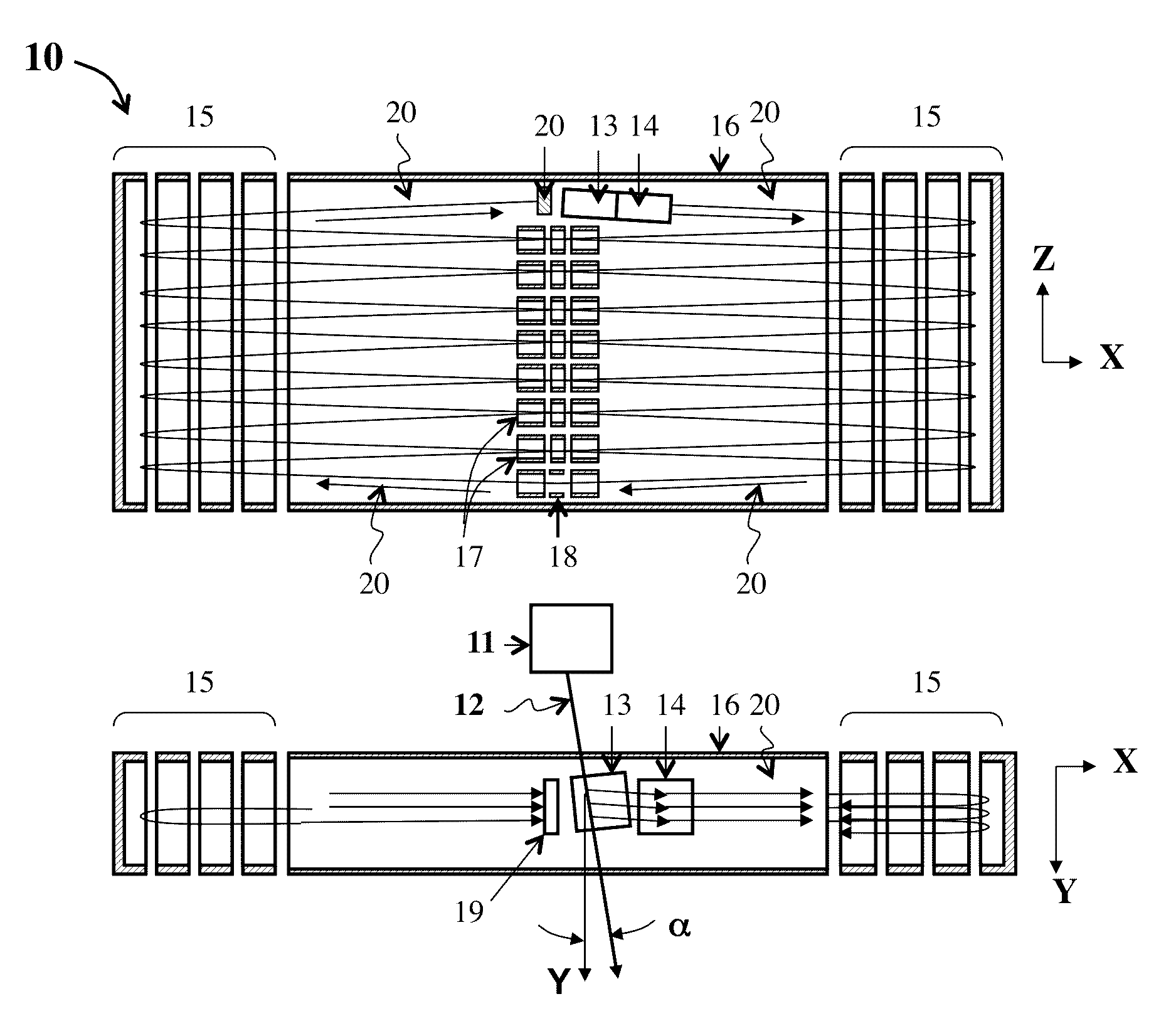
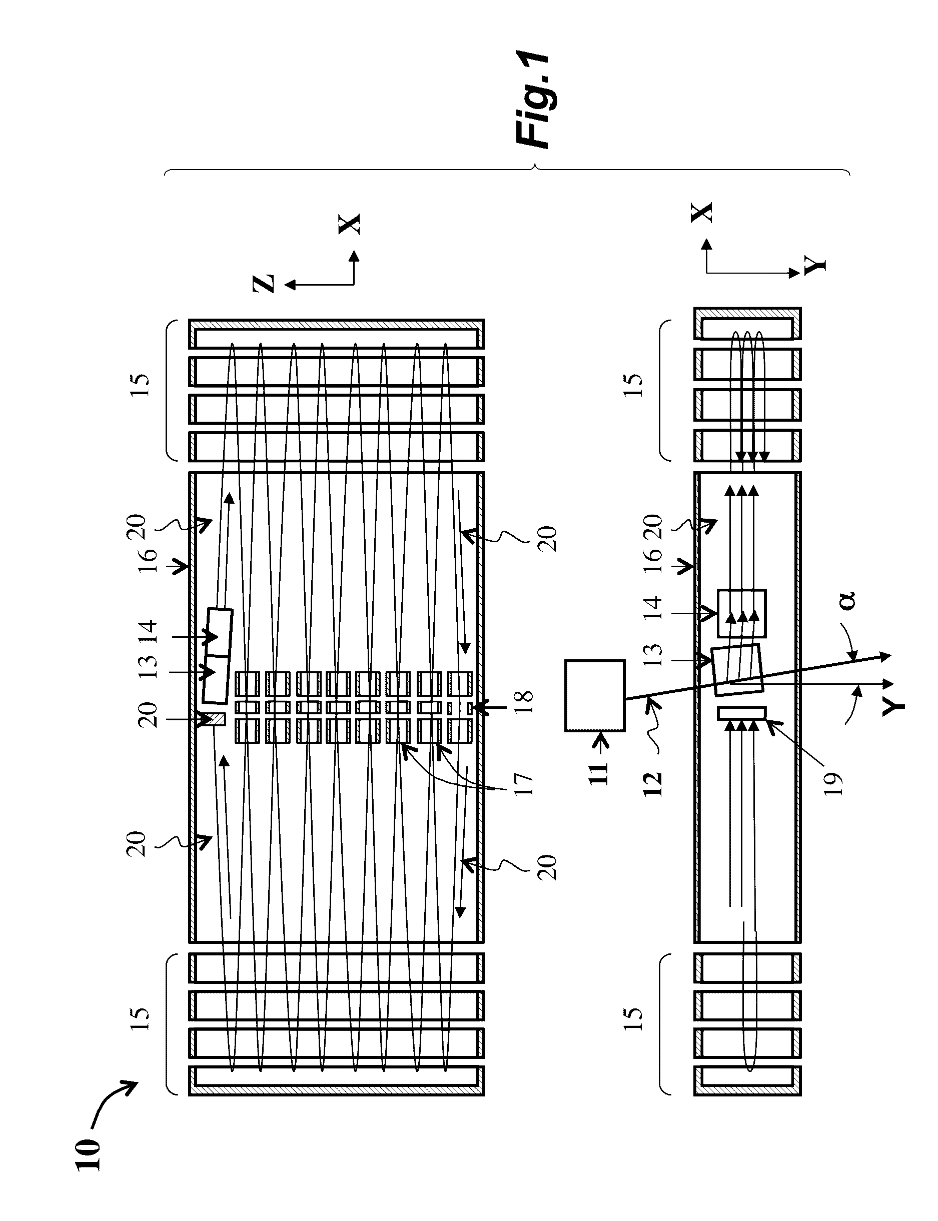
[0056]Referring to FIG. 1, an embodiment 10 of a MR-TOF MS utilizing an orthogonal accelerator (OA) 13 of WO2007044696, which is incorporated herein by reference, comprises a continuous ion source 11, the OA 13 with a steering lens 14, a pair of parallel and gridless ion mirrors 15 separated by a negatively floated drift space 16, a periodic lens 17 with a steering deflector 18, and a detector 19. In operation, a well-directed continuous ion beam 12 is introduced into OA substantially along the Y-axis. Periodic pulses (not shown), which are applied to plates of the OA 13, accelerate ion ribbon packets into the drift space of the MR-TOF MS and along a jigsaw trajectory 20. At the OA 13, the trajectory of the ion beam is offset from the Y-axis at a small angle α, which enables compensation for time-of-flight aberrations at ion beam steering, while using a finite energy level for the ion beam 12 between 20 eV and 100 eV.

[0057]Practical implementations of the scheme illustrated in FIG. ...

embodiment 41

[0107]Referring to FIG. 4, a preferred embodiment 41 of time-of-flight mass spectrometer performing the axial bunching method 31 of the disclosure includes the following sequentially and axially aligned components: a continuous source 42, a continuous acceleration stage 43 (i.e. an accelerator), a spatially focusing lens 44, a suppresser 45, a buncher formed with parallel electrodes 46 and 48, an energy filter 49, and a TOF analyzer 50, which may be either Re-TOF or MR-TOF. Pulse generators, depicted by gate icons, are connected to electrodes 45 and 46.

[0108]In operation, a suitable continuous ion source 42 generates a continuous ion beam (shown in FIG. 4 by a white arrow) with less than 10 eV energy spread ΔK, and more preferably ΔK42 generates ions in a wide mass range as presented by black circles of different size. The accelerator 43 continuously accelerates the ion beam to a mean energy KC, which at least ten times larger than the energy spread ΔK. The absolute velocity spread ...

embodiment 71

[0117]Referring to FIG. 7A, an embodiment 71 of the pulsed converter optionally includes a closed electron impact (EI) ion source 42, an electrostatic acceleration stage 43, an axial symmetric lens 44, a gridless buncher 47 depicted between entrance section 46 and exit section 48, and an energy filter 79. The gridless buncher 47 may optionally be embodied as the buncher illustrated in FIG. 6A. The energy filter 79 comprises a planar lens 72, a first electrostatic sector 73, a second electrostatic sector 74, a third electrostatic sector 75, a set of surrounding slits 76, and an energy filtering slit 77.

[0118]The closed EI ion source 42, which is grounded, generates an ion beam with an energy spread of approximately 1 eV. After accelerating the ion beam to 1500 eV at the electrostatic acceleration stage 43 (floated to −1500V), the ion beam emittance is estimated as 2 mm*deg, based on experimental data. The axial symmetric lens 44 provides spatial focusing at a middle of the buncher 47...


PUM


Abstract

Apparatuses (41, 91, 111, 115, 121, 151) and methods (31) for time-of-flight mass spectrometry providing effective pulsed conversion of continuous ion beams into pulsed ion packets is disclosed. Bunching of energetic continuous ion beams forms ion packets, which are filtered by a subsequent isochronous energy filter (49, 79, 81-84, 110). The bunching method is particularly suitable for ion sources with relatively large spatial emittance, otherwise unable to fir the acceptance of orthogonal accelerators. The method is particularly suitable for multi-reflecting TOF MS, which accommodates small size ion packets and where the duty cycle advantage of orthogonal accelerators is minor.

Description

TECHNICAL FIELD[0001]This disclosure relates to time-of-flight mass spectroscopic analysis and to an improved method of pulsed ion conversion for singly reflecting and multi-reflecting time-of-flight mass spectrometers.BACKGROUND[0002]Time-of-flight mass spectrometers (TOF MS) determine the mass-to-charge ration (m / z) of an ion by accelerating ions through the TOF MS towards a detector and recording a measurement for the ion travel time within the TOF MS to the detector. Some implementations have utilized two TOF MS consecutively (TOF / TOF). Other implementations of TOF MS may include gas chromatography (GC-TOF MS) or liquid chromatography (LC-TOF MS) to handle a sample before TOF MS carry out the analysis. Additionally, such implementations of GC-TOF MS and LC-TOF MS may utilize a quadrupole ion trap (LC-Q-TOF and GC-Q-TOF), such as U.S. Patent Application 2013 / 0068942 incorporated herein by reference.[0003]Parameters of TOF MS depend on efficient coupling to pulsed and continuous i...

Claims


Application Information

Patent Timeline
IPC IPC(8): H01J49/40H01J49/00G01N30/72
CPCH01J49/403H01J49/406H01J49/0031G01N30/72H01J49/44H01J49/06
Inventor VERENCHIKOV, ANATOLY N.
Owner LECO CORPORATION
Why Eureka
Try Eureka