
Temperature sensor for tracking body temperature based on printable nanomaterial thermistor

a nanomaterial and temperature sensor technology, applied in the field of thermometers, can solve the problems of insufficient temperature sensing accuracy of electronic sensors, inability to track body temperature, and long time-consuming thermometers, etc., and achieve the effect of fast and accurate tracking of body temperature and excellent thermal insulation

Active Publication Date: 2017-05-11
NANO & ADVANCED MATERIALS INST
View PDF10 Cites 9 Cited by
  • Summary
  • Abstract
  • Description
  • Claims
  • Application Information

AI Technical Summary

Benefits of technology

The patent describes a printable thermistor that can be used to track body temperature accurately. The thermistor is made by printing a Si—C film onto a substrate and connecting it to control circuitry using electrodes. The device is designed to prevent moisture from getting inside, which can cause damage. The temperature sensor is well-insulated and can provide fast and accurate readings.

Problems solved by technology

Smart / wearable devices for body temperature tracking are becoming more and more challenging based on traditional temperature sensing technologies.
These electronic sensors don't have enough accuracy for temperature sensing when becoming wearable on a human body since the thermal contact area is limited.
It is challenging for these sensors to build up thermal equilibriums with the human body under ambient environments, and thus these thermometers take a very long time to measure the body temperature, such as 10-15min or much longer.
There are also some flexible thin films of platinum sensors for temperature but their area is limited to 1 mm-2 mm since Pt is quite expensive.
Therefore, it is very difficult for traditional sensors to continuously monitor and track physiological signals as smart / wearable devices, especially when biometric information on the human body almost changes every second.

Method used


Image

  • Temperature sensor for tracking body temperature based on printable nanomaterial thermistor
  • Temperature sensor for tracking body temperature based on printable nanomaterial thermistor
  • Temperature sensor for tracking body temperature based on printable nanomaterial thermistor

Examples


example 1

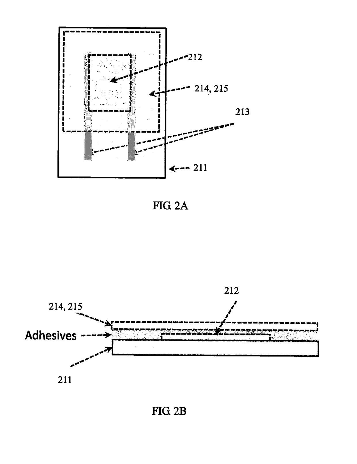
[0055]A fully printable NTC thermistor was produced on an 80 μm-thick PET substrate according to the design in FIG. 3. Two electrodes with a distance of about 1 mm were printed using DuPont 5064H silver conductor material and subsequently cured under ambient conditions. Afterwards, printing paste containing Si NPs and graphite flakes was printed with an area of 15 mm*20 mm, and a continuous film was made to cover above two Ag electrodes (as shown in FIG. 3). The Si—C composites were formed by mixing Si NPs and graphite flakes. The silicon nanoparticles were non-doped silicon nanopowders from MTI Corporation, which had a particle size of about 80 nm and single crystal nanostructures produced by plasma synthesis. The graphite flakes were polar Graphene platelets from Angstron Materials Inc, with thickness of about 10-20 nm and lateral size <14 μm. About 10% graphite flakes were mixed in the Si—C composites. The details of formulas for the Si—C paste were shown as below formula 1. Even...

example 2

[0065]In a second example, another fully printable NTC thermistor was produced according to the design in FIG. 3. Two interdigitated silver electrodes were deposited on a 50 μm-thick LCP substrate by screen printing using DuPont 5064H silver conductor. Ten pairs of fingers were prepared for the Ag electrodes, with finger width of about 0.3 mm and adjacent separation of about 1 mm. Then, an area of 15 mm*25 mm was defined for Si—C nanocomposite paste printing. The Si—C composites were formed by mixing Si NPs and graphite flakes. The silicon nanoparticles were non-doped silicon nanopowders from MTI Corporation, which had a particle size of about 80 nm and single crystal nanostructures produced by plasma synthesis. The graphite flakes were polar Graphene platelets from Angstron Materials Inc, with thickness of about 10-20 nm and lateral size below 14 μm. About 10% graphite flakes were mixed in Si—C composites. The formula for the Si—C paste was followed as formula 1 described above. Th...

example 3

[0066]In a third example, still another fully printable NTC thermistor was also fabricated according to the design in FIG. 3. Two interdigitated silver electrodes were deposited on a 50 μm-thick LCP substrate by screen printing using DuPont 5064H silver conductor. Ten pairs of fingers were prepared for the Ag electrodes, with finger width of about 0.3 mm and adjacent separation of about 1 mm. Then, an area of 15 mm*25 mm was defined for Si—C nanocomposite paste printing. The Si—C composites were formed by mixing Si NPs and graphite flakes. The silicon nanoparticles were non-doped silicon nanopowders from MTI Corporation, which had a particle size of about 80 nm and single crystal nanostructures produced by plasma synthesis. The graphite flakes were polar Graphene platelets from Angstron Materials Inc, with thickness of about 10-20 nm and lateral size below about 14 μm. About 10% graphite flakes were mixed in Si—C composites. The formula for Si—C paste was followed as formula 1 descr...


PUM


Abstract

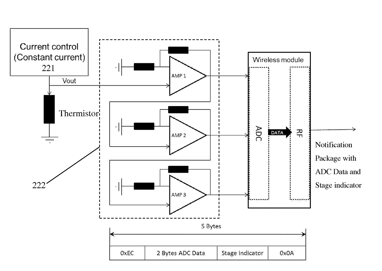
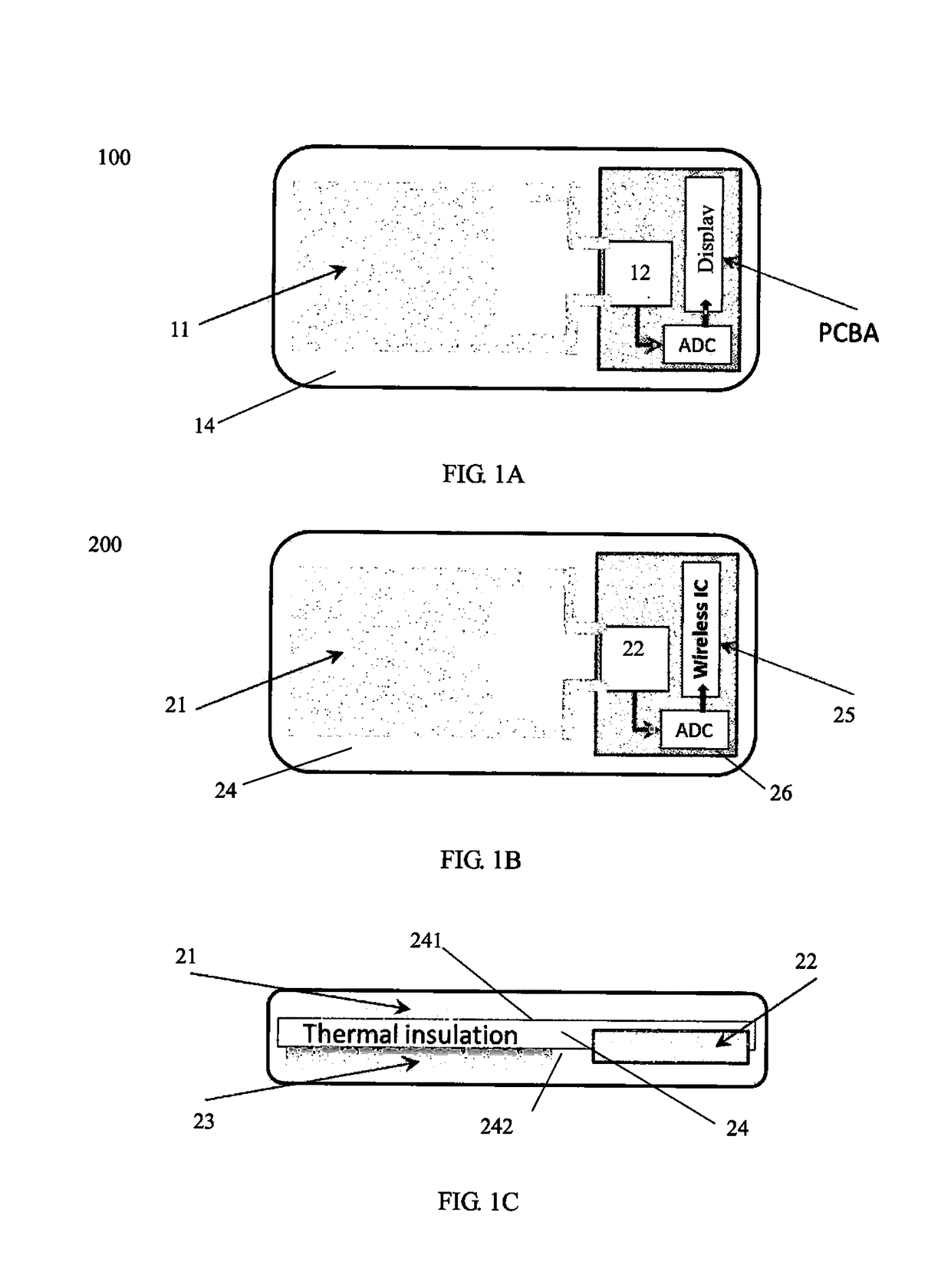
Provided are wireless temperature sensors. A temperature sensor with a flexible, large-area printed thermistor can include an negative temperature coefficient (NTC) thermistor for temperature sensing, a control circuitry for electrically connecting with the NTC thermistor and obtaining the temperature sensed by the NTC thermistor, a power source for providing power supply to the NTC thermistor and the control circuitry, and a frame element for supporting the NTC thermistor, the control circuitry and the power source, where the frame element is at least partially thermally insulated to establish thermal equilibrium within the temperature sensor. The temperature sensor can sense the temperature in a fast and accurate way due to fast thermal equilibrium established within the sensor.

Description

TECHNICAL FIELD[0001]This disclosure generally relates to a thermometer field, and particularly to temperature sensors for tracking body temperature based on printable nano-material technology.BACKGROUND[0002]Smart / wearable devices for body temperature tracking are becoming more and more challenging based on traditional temperature sensing technologies. Electronic sensors for temperature are typically composed of tiny tips of negative temperature coefficient (NTC) ceramic materials, platinum (PT-100) or infrared photo-devices. These electronic sensors don't have enough accuracy for temperature sensing when becoming wearable on a human body since the thermal contact area is limited. It is challenging for these sensors to build up thermal equilibriums with the human body under ambient environments, and thus these thermometers take a very long time to measure the body temperature, such as 10-15min or much longer. There are also some flexible thin films of platinum sensors for temperatu...

Claims


Application Information

Patent Timeline
IPC IPC(8): A61B5/00G01K1/08G01K7/22H01C17/28A61B5/01H01C1/142H01C1/14H01C7/04G01K13/00
CPCA61B5/0008H01C7/041G01K1/08G01K7/22G01K13/002A61B5/01A61B2562/12H01C1/142H01C1/1413H01C17/281A61B2560/0214A61B2562/0209A61B2562/0276A61B5/0022G01K7/226A61B2562/164G01K13/20
Inventor SUN, CAIMING
Owner NANO & ADVANCED MATERIALS INST
Learn More