Noncrystallizable sensitized layers for OLED and oeds

a sensitized layer and non-crystallizable technology, applied in the direction of luminescent compositions, semiconductor devices, chemistry apparatus and processes, etc., can solve the problems of materials crystallizing, many problems to be solved, and the properties desired for oled applications are generally only observed

Inactive Publication Date: 2017-06-08
MOLAIRE CONSULTING
View PDF6 Cites 2 Cited by
  • Summary
  • Abstract
  • Description
  • Claims
  • Application Information

AI Technical Summary

Benefits of technology

[0029]Accordingly, the invention provides a light emitting device comprising: a light emitting layer comprising an electroluminescent organic material dispersed in a matrix, wherein the electroluminescent organic material has molecular weight less than about 2000 atomic mass units (amu), the matrix comprises a non-electroluminescent non-crytstallizable molecular glass mixture, and each of the non-electroluminescent non-crytstallizable molecular glass mixture and the electroluminescent organic material constitutes at least about 20 percent by weight of the light emitting layer; and electrodes in electrical communication with the light emitting layer and configured to conduct an electric charge through the light emitting layer such that the light emitting layer emits light.

Problems solved by technology

Of course many problems have to be solved before these possibilities become reality.
However, the properties desired for OLED applications are generally only observed in solution or at low levels of doping in electro-optical or electroactive polymers.
In the solid state, these materials can crystallize and lack the mechanical integrity to be utilized in POLEDs or SMOLEDs.
Additionally (and more importantly), the excellent fluorescence and electroluminescence is lost with crystallization.
If the Tg of the polymer / laser dye is exceed, crystallization of the laser dye could occur thus limiting the electroluminescent efficiency of the device.
It is well known by those versed in the art that such glass will eventually crystallize thermodynamically, resulting in performance degradation of the device.

Method used


Image

  • Noncrystallizable sensitized layers for OLED and oeds
  • Noncrystallizable sensitized layers for OLED and oeds
  • Noncrystallizable sensitized layers for OLED and oeds

Examples


example 1

on of the Glass Mixture Example 1

[0243]Recrystallized 3′,3″,5′, 5″-tetrabromobisphenol A 178.3894 g (0.328 mole), distilled isobutyryl chloride 13.98 g (0.1312 mole), distilled benzoyl chloride 18.44 (0.1312 mole), and distilled 4-bromobenzoyl chloride 14.397 g (0.0656 mole), all are dissolved in approximately 1 liter of 1,2-dichloroethane, in a three-neck, round-bottomed flask. A condenser fitted with a drying tube and a positive-pressure nitrogen system is used to keep moisture out of the reactor vessel.

[0244]Triethylamine 70.5 g (0.697 mole) dissolved in 100 ml of 1,2-dichloroethane is added dropwise to the stirred solution in the reaction flask. After complete addition of the triethylamine, the reaction is allowed to continue for three additional hours at which time the precipitated salt is filtered off. The solution is subjected to the following extraction sequence:

[0245]a) two dilute sodium hydroxide solution washes (2% cold);

[0246]b) two dilute hydrochloric acid solution wash...

example 2

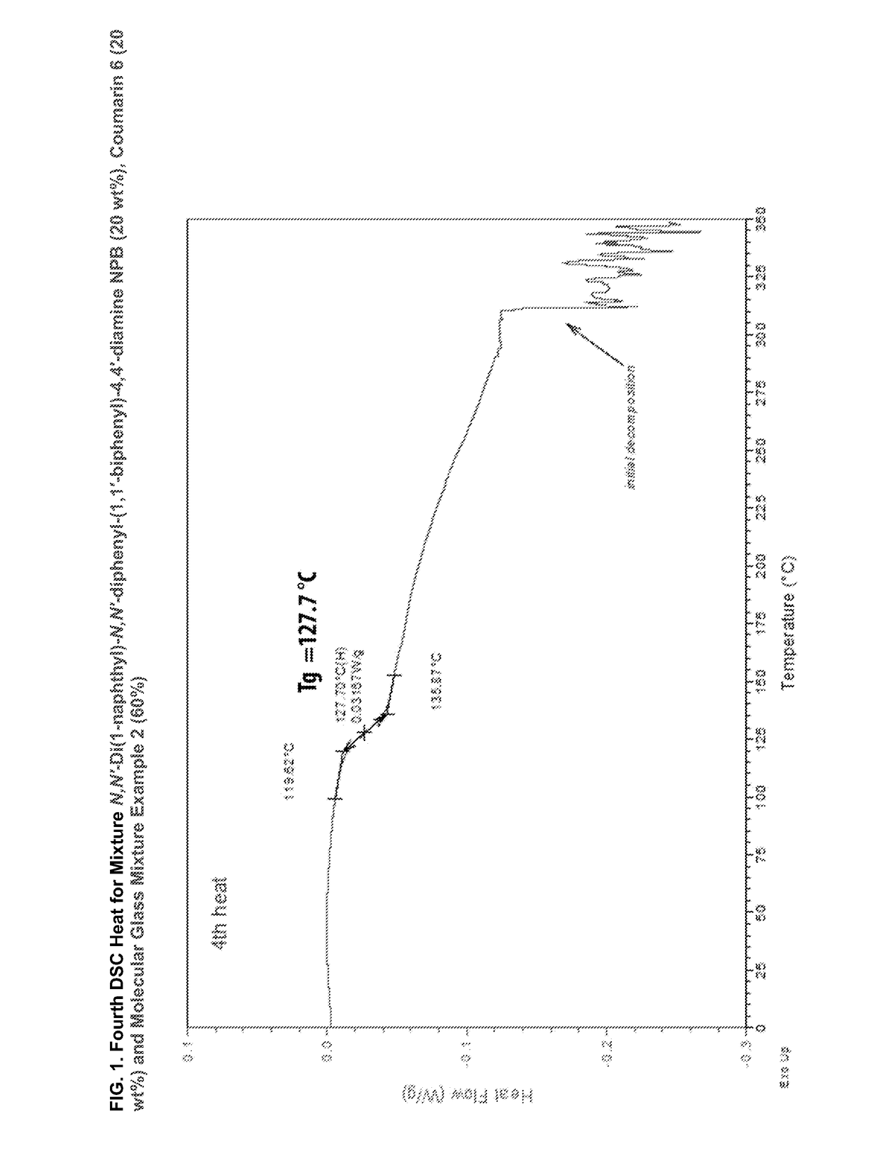
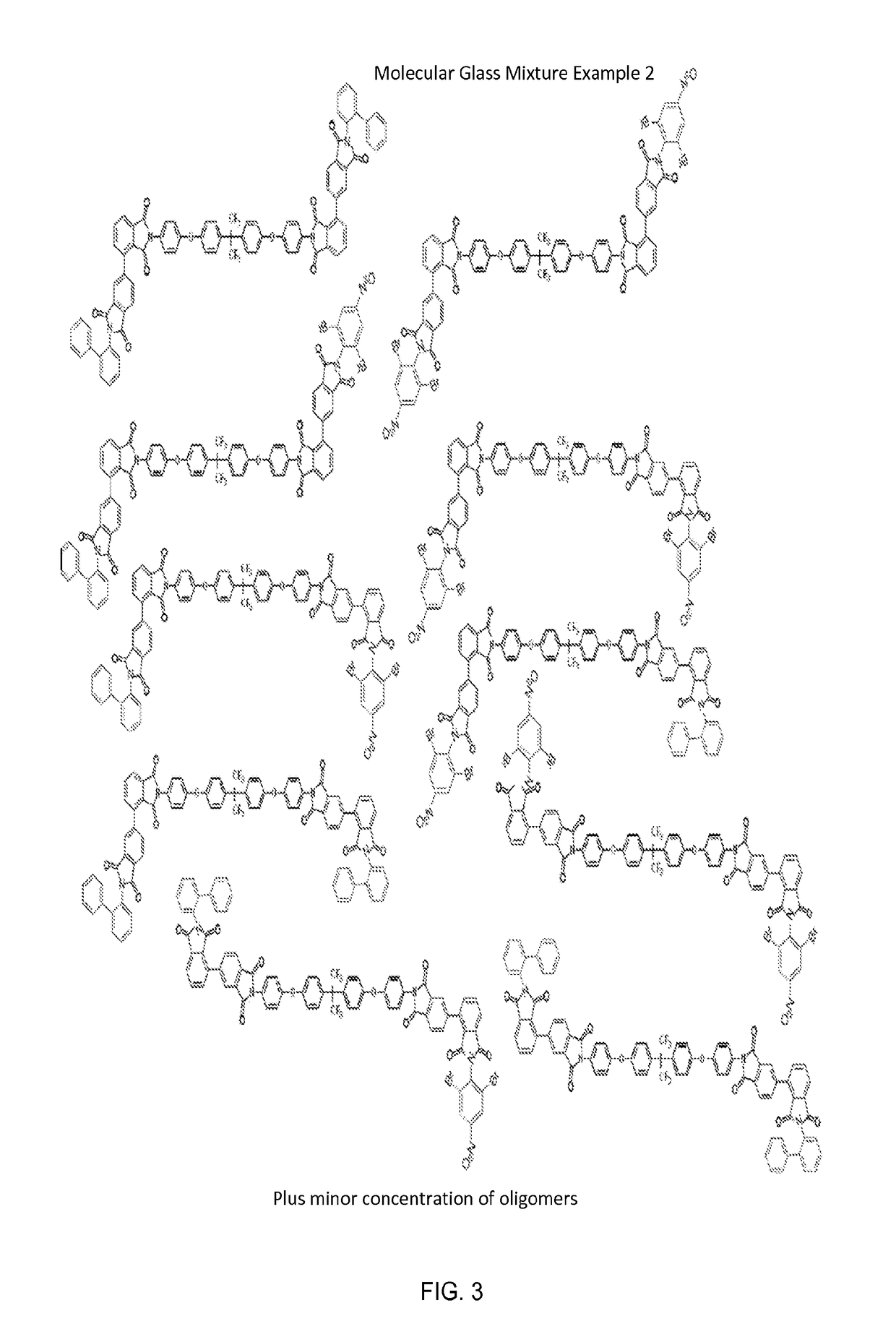
on of the Glass Mixture Example 2

[0249]In a 500 milliliter three-necked round-bottomed flask, fitted with a condenser were added 400 ml of anhydrous NMP solvent. Then 15.56 g (0.030 mole) of recrystallized 2,2-Bis[(4-aminophenoxy)phenyl]hexafluoropropane (HFBAPP) (Akron Polymer Systems) and 17.65 g (0.060) mole) of diphenyl-2,3,3′,4′-tetracarboxylic dianhydride (a-BPDA)) (Akron Polymer Systems), and 8.52 (0.066 mole) of isoquinoline (catalyst) were added. The mixture was gently heated to 70° C. under stirring for 2 hours. The intermediate mixture is shown below

[0250]Plus Minor Concentration of Oligomers

[0251]Then 5.08 g (0.03 mole) of recrystallized 2-aminobiphenyl (Aldrich), and 8.439 (0.03 mole) of recrystallized 2,5-dibromonitrobenzene (Aldrich) were added to the reaction vessel. The mixture was gently heated to 70° C. under stirring for another 2 hours, followed by refluxing for 5 hours. Thereafter, the mixture was poured into a mixture of methanol and dilute hydrochloric acid u...

example 3 compatibility

of 2-(4-tert-Butylphenyl)-5-(4-biphenylyl)-1,3,4-oxadiazole, “ButylPBD” and Molecular Glass Mixture Example 1

[0253]Compatibility was assessed by differential scanning calorimetry (DSC) of mixtures of the two materials at a rate of 10° C. / min under nitrogen at a flow rate of 50 cc / min. The two components were first weighed separately and then blended in the proper ratio by weight. The blend was then manually mixed, pulverized and remixed several times by hand in a glass petri dish. FIG. 4 shows the DSC scan (2nd heat) for neat ButylPBD. No glass transition temperature (Tg) is measured, even after all four runs. A sharp melting is seen at 138° C. These results are tabulated in Table 3. Also on Table 3 the results for Molecular glass mixture example 1 are show: no crystallization (Tc) and melting peaks (melt temperature (Tm)) after all four runs; only a Tg is measured at 59° C.

[0254]The second DSC heat for the 50 / 50 mixture of molecular glass mixture example 1 and ButylPBD is shown on ...


PUM

PropertyMeasurementUnit
Tgaaaaaaaaaa
Tgaaaaaaaaaa
Tgaaaaaaaaaa

Abstract

Various embodiments of the present invention provide for a light emitting devices comprising a light emitting layer comprising an electroluminescent organic material dispersed in a matrix, wherein the electroluminescent organic material has a molecular weight less than about 2000 amu, the matrix comprises a nonelectroluminescent-nonpolymeric amorphous glass mixture, and each of the nonelectroluminescent-nonpolymeric organic molecular glass mixture and the electroluminescent organic material constitutes at least 20 percent by weight of the light emitting layer; and electrodes in electrical communication with the light emitting layer and configured to conduct an electric charge through the light emitting layer such that the light emitting layer emits light.

Description

TECHNICAL FIELD[0001]This invention relates to organic electroluminescent devices and more specifically to noncrystallizable light-emitting layer compositions.BACKGROUND ART[0002]Organic Light emitting diode (OLED) and other organic electronic technologies such as organic photovoltaics (OPV) and organic field effect transistors are expected to be a major opportunity for advanced materials development impacting a large number of future technology based applications. These include flat panel displays which offer significant advantages over liquid crystal displays (LCDs) including much lower power requirements, improved definition, broader viewing angles, and faster response times. The technology for OLEDs offers the potential for lower cost lighting sources compared to incandescent lighting as well as fluorescent lighting applications. Inorganic based LEDs are already replacing some of these conventional applications including traffic lighting as well as flashlights offering equal or ...

Claims


Application Information

Patent Timeline
Patent Type & Authority Applications(United States)
IPC IPC(8): H01L51/00C09K11/02C09K11/06
CPCH01L51/0072C09K2211/1014H01L51/005H01L51/0052H01L51/0073H01L51/007C09K11/06C09K11/025H01L51/0071H01L51/006H01L51/5012H01L51/5016H01L51/56H01L51/0003H01L51/0005H01L2051/0063C09K2211/1007C09K2211/1048C09K2211/1037C09K2211/1088H01L51/0058C09K2211/1011H01L51/0053H10K50/11H10K85/6572H10K85/60H10K85/615H10K85/621H10K85/633H10K85/657H10K85/6565H10K85/6574H10K71/00H10K71/12H10K71/135H10K85/626H10K2101/10
Inventor MOLAIRE, MICHEL FRANTZ
Owner MOLAIRE CONSULTING
Why Eureka
Try Eureka