
Abradable Compositions and Methods for CMC Shrouds

a composition and composition technology, applied in the direction of blade accessories, metallic material coating process, machine/engine, etc., can solve the problems of loss of efficiency, damage to the blade set, and even more likely damage to the metal blad

Active Publication Date: 2017-06-15
GENERAL ELECTRIC CO
View PDF3 Cites 23 Cited by
  • Summary
  • Abstract
  • Description
  • Claims
  • Application Information

AI Technical Summary

Benefits of technology

The technical effects of this invention are not specified in this particular section of the text. However, its advantages may be inferred from the description and practice of the invention.

Problems solved by technology

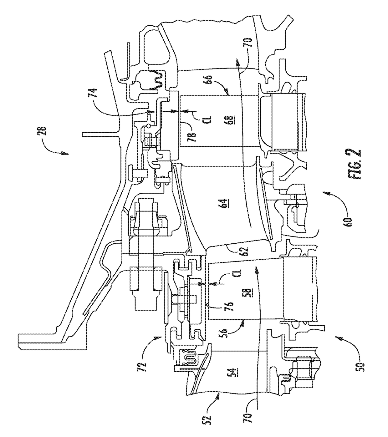
During engine operation, the blade tips can sometime rub against the shroud, thereby increasing the gap and resulting in a loss of efficiency, or in some cases, damaging or destroying the blade set.
For CMC shrouds, damage to a metal blade is even more likely, since the silicon carbide material is significantly harder than the Nickel-based superalloys.
Thus, if rub from a blade tip takes off the coating, the CMC shroud is left susceptible to high temperature steam recession.
The patterned ridges on the surface of the shroud, however, lead to aerodynamic losses to the efficiency of the engine.
Additionally, it is difficult to produce a thick, continuous layer of the EBC materials (>20 mils) without spallation.

Method used


Image

  • Abradable Compositions and Methods for CMC Shrouds
  • Abradable Compositions and Methods for CMC Shrouds
  • Abradable Compositions and Methods for CMC Shrouds

Examples


Embodiment Construction

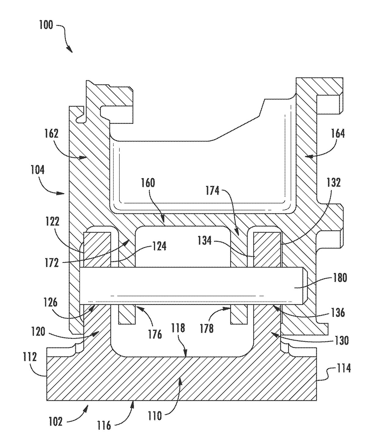
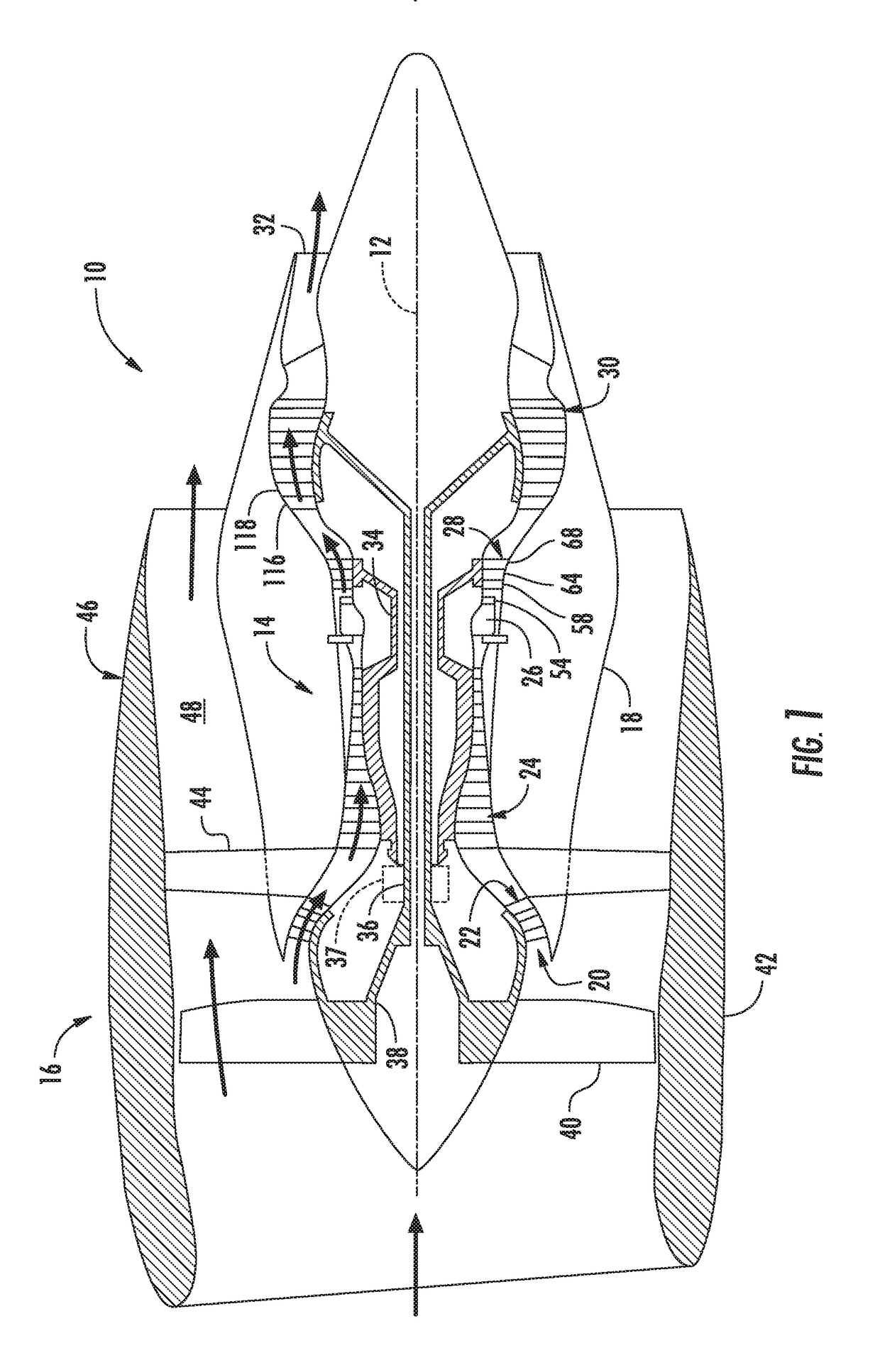
[0023]Reference now will be made in detail to embodiments of the invention, one or more examples of which are illustrated in the drawings. Each example is provided by way of explanation of the invention, not limitation of the invention. In fact, it will be apparent to those skilled in the art that various modifications and variations can be made in the present invention without departing from the scope or spirit of the invention. For instance, features illustrated or described as part of one embodiment can be used with another embodiment to yield a still further embodiment. Thus, it is intended that the present invention covers such modifications and variations as come within the scope of the appended claims and their equivalents.

[0024]As used herein, the terms “first”, “second”, and “third” may be used interchangeably to distinguish one component from another and are not intended to signify location or importance of the individual components.

[0025]The terms “upstream” and “downstre...


PUM

PropertyMeasurementUnit
Porosityaaaaaaaaaa
Compositionaaaaaaaaaa
Porosityaaaaaaaaaa

Abstract

Coating systems on a surface of a CMC component, such as a CMC shroud, are provided. The coating system can include an environmental barrier coating on the surface of the CMC component and an abradable coating on the environmental barrier coating and defining an external surface opposite of the environmental barrier coating. The abradable coating includes a compound having the formula: Ln2ABO8, where Ln comprises scandium, yttrium, lanthanum, cerium, praseodymium, neodymium, promethium, samarium, europium, gadolinium, terbium, dysprosium, holmium, erbium, thulium, ytterbium, lutetium, or mixtures thereof; A comprises Si, Ti, Ge, or a combination thereof; and B comprises Mo, W, or a combination thereof. In one embodiment, the abradable coating has a first coefficient of thermal expansion at an interface with the environmental barrier coating that changes to a second coefficient of thermal expansion at its external surface. Methods are also provided for applying an abradable coating onto a CMC component.

Description

FIELD OF THE INVENTION[0001]Embodiments of the present invention generally relate to thermal and environmental barrier coatings for ceramic components, particularly for use on a CMC shroud in a gas turbine engine.BACKGROUND OF THE INVENTION[0002]The turbine section of a gas turbine engine contains a rotor shaft and one or more turbine stages, each having a turbine disk (or rotor) mounted or otherwise carried by the shaft and turbine blades mounted to and radially extending from the periphery of the disk. A turbine assembly typically generates rotating shaft power by expanding hot compressed gas produced by combustion of a fuel. Gas turbine buckets or blades generally have an airfoil shape designed to convert the thermal and kinetic energy of the flow path gases into mechanical rotation of the rotor.[0003]Within a turbine engine, a shroud is a ring of material surrounding the rotating blades. Turbine performance and efficiency may be enhanced by reducing the space between the tip of ...

Claims


Application Information

Patent Timeline
IPC IPC(8): F01D9/04C04B41/50C04B41/89
CPCF01D9/04C04B41/89C04B41/5072F05D2300/611F05D2230/90F05D2300/6033F05D2300/17F05D2220/32C23C4/04F01D25/005F01D25/24F05D2300/5021C04B35/495C04B35/565C04B35/80C04B41/009C04B41/52C04B2111/00405C04B2235/3224C04B2235/3225C04B2235/3227C04B2235/3229C04B2235/3232C04B2235/3287C04B2235/3418F01D5/288F01D11/001F01D11/122F05D2300/13F05D2300/131F05D2300/15C04B35/806C04B41/5096C04B41/5024C04B2103/0021C04B2103/001C04B41/524C04B41/526C04B41/5027
Inventor KIRBY, GLEN HAROLDMANICKE, PAUL STEPHEN
Owner GENERAL ELECTRIC CO
Learn More