Amphiphilic nanosheets and methods of making the same

Inactive Publication Date: 2017-06-22
TEXAS A&M UNIVERSITY
View PDF0 Cites 15 Cited by
  • Summary
  • Abstract
  • Description
  • Claims
  • Application Information

AI Technical Summary

Benefits of technology

[0060]The aforementioned methods of making amphiphilic nanosheets provide numerous advantages. In particular, the methods of the present invention provide a facile and continuous method of making bulk quantities of Janus and Gemini particles. Previous methods of producing such particles involved multiple steps, the use of protecting agents to protect half of the spheres first, and the need to get rid of the agents later.
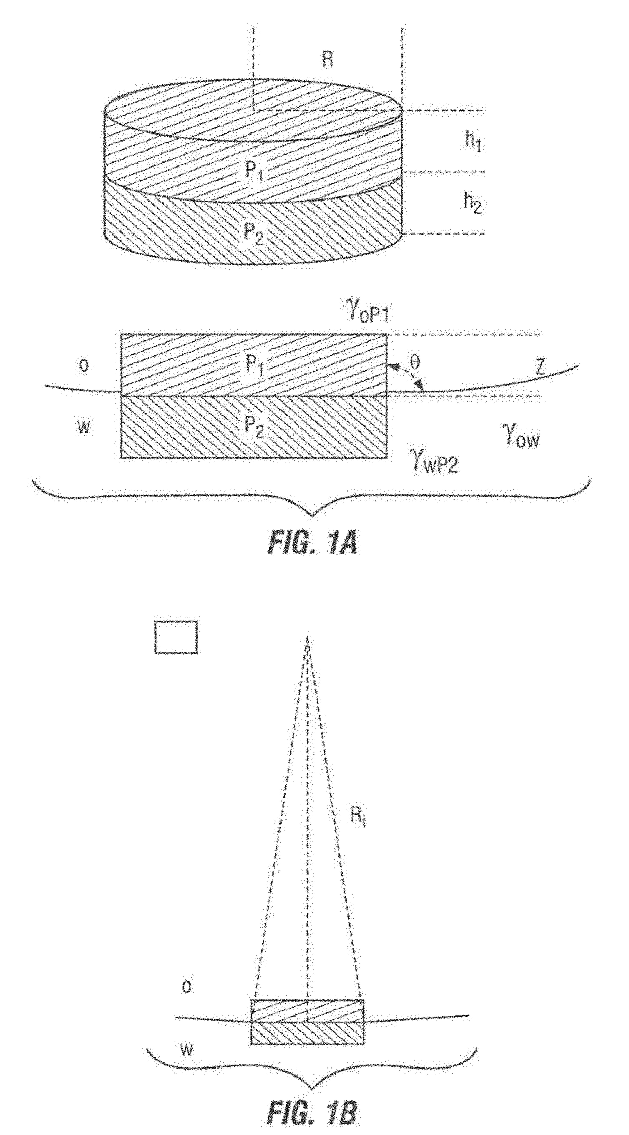
[0061]The amphiphilic nanosheets of the present invention also provide numerous advantages. By way of background, there are opposite effects in the stabilization of Pickering emulsions (emulsions stabilized by particles) using spherical particles. For instance, stabilization requires particles as small as possible. However, smaller particles are easy to escape the interface due to Brownian motion since the adsorption energy to the oil-water interface is proportional to the diameter of the spheres. In fact, it has been found that anisotropic particles with high aspect ratios are better emulsion stabilizers.
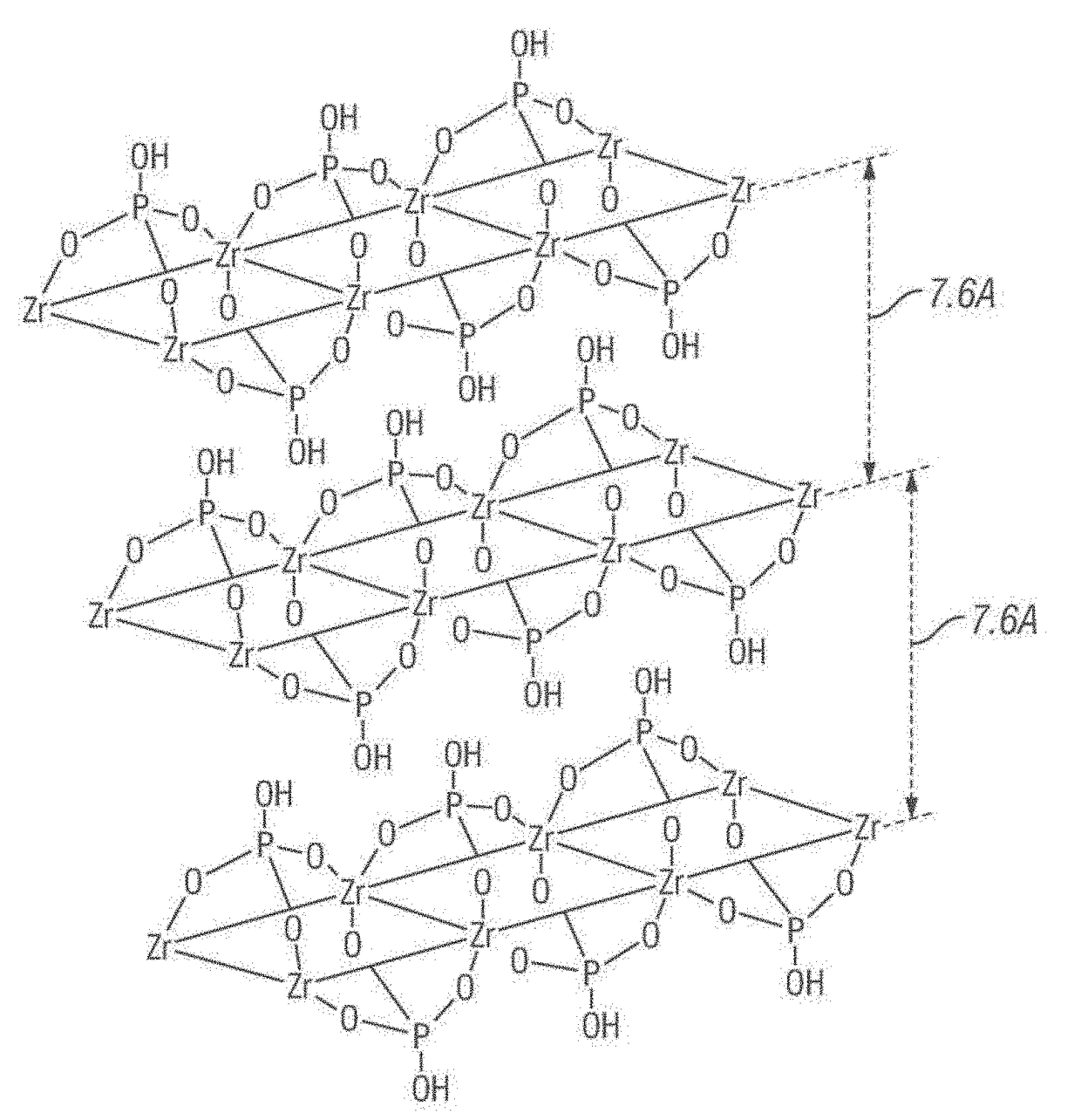
[0062]As set forth in more detail in the Examples below, the amphiphilic nanosheets of the present invention (such as α-zirconium phosphate platelets) have established a platform for flexible design of multifunctional surfactants tailored for optimal performance. In particular, the highly anisotropic and amphiphilic nanosheets of the present invention reconcile the aforementioned opposite effects due to the existence of length scales, thicknesses, and lateral size(2Rd).
[0063]The large aspect ratios of the amphiphilic nanosheets also offer optimal stability to the nanosheets between two emulsions to prevent coalescence.

Problems solved by technology

Current surfactants have numerous limitations in terms of solubility, durability and effectiveness.
Cu

Method used


Image

  • Amphiphilic nanosheets and methods of making the same
  • Amphiphilic nanosheets and methods of making the same
  • Amphiphilic nanosheets and methods of making the same

Examples


Example

EXAMPLE 1

Grafting and Exfoliation of α-ZrP

[0078]α-ZrP is characterized by a strong hydrophilicity. Hence, chemical modification is required to convert it to become hydrophobic. First, a coupling agent is grafted over the exposed edges and flat surfaces of the α-ZrP crystals. See FIG. 3 (grafting step). Subsequently, via the exfoliation of these crystals, a mixture of thin-surface and edge-modified amphiphilic nanosheets are obtained from the outer and the inner layers, respectively. See FIG. 3 (exfoliation step) and FIGS. 4A-4D (showing the transmission electron microscope (TEM) images of the α-ZrP nanosheets).

[0079]As shown in FIGS. 4A-4D, the α-ZrP nanosheets are thin and flexible, and can present wrinkles, as shown in FIGS. 4B and 4C. This demonstrates that the nanosheets can bend on the oil-water interface to stabilize the emulsions. It has been proven that the single nano-plate layer is rigid when the nanosheet size is about several tenths of a nanometer or less and becomes fle...

Example

EXAMPLE 2

Synthesis and Functionalization of α-ZrPs

[0083]The synthesis of the highly crystalline α-ZrP by the hydrothermal method has been described by Sun et al. Sun, L. Y.; Boo, W. J.; Sue, H. J.; Clearfield, A. New J. Chem. 2007, 31, 39. Particularly, 6 g ZrOCl28H2O were mixed with 60 mL (9 M) H3PO4 and heated at 200° C. for 24 hours in a high-pressure autoclave. After the reaction, the product was centrifuged and washed three times with deionized (DI) H2O and dried overnight at 60° C. The dried product was ground with a mortar and pestle into a fine powder. Highly crystalline α-ZrP was used to avoid the intercalation of the modifier in the surface and edge modification step. Finally, the crystals were reacted with octadecyl isocyanate (Aldrich, 98%) in a 1:10 (ODI:ZrP) molar ratio at 65° C., using o-xylene as a solvent, for 12 hours under nitrogen. The resulting product was washed with methanol three times and dried at 60° C. overnight in an oven.

Example

EXAMPLE 3

Characterization of the Modified α-ZrPs

[0084]The resulting powder was characterized by Fourier transform infrared (FTIR, Shimadzu IRAffinity-1 spectrometer in an ATR, attenuated total reflection mode with a ZnSe ATR Prism Model Pike MIRacle A, Columbia, Md.) and thermogravimetric analysis (TGA, Q500 TA Instrument, New Castle, Del.). AFM images were collected with an Agilent / Molecular Imaging PicoSPM coupled with an RHK Technology SPM 1000 Electronics Revision 8, and X-ray photoelectron spectroscopy (XPS, Kratos Axis Ultra Imaging, Chestnut Ridge, N.Y.) to analyze the elementary composition of the final compound.

Fourier Transform Infrared Spectroscopy (FTIR)

[0085]The grafting reactions (i.e., the outer surface modification reactions) were analyzed by Fourier transform infrared spectroscopy (FTIR). See FIG. 7. The FTIR spectrum of pristine α-ZrP is shown in Graph 1 of FIG. 7. Applicants observed that the isocyanate band (—N═C═O) at 2260 cm−1 (shown in FIG. 7, Graph 2) vanishe...


PUM

PropertyMeasurementUnit
Thicknessaaaaaaaaaa
Thicknessaaaaaaaaaa
Diameteraaaaaaaaaa

Abstract

In some embodiments, the present invention provides amphiphilic nanosheets that comprise lamellar crystals with at least two regions: a first hydrophilic region and a second hydrophobic region. In some embodiments, the amphiphilic nanosheets of the present invention also comprise a plurality of functional groups that are appended to the lamellar crystals. In some embodiments the functional groups are hydrophobic functional groups that are appended to the second region of the lamellar crystals. In some embodiments, the lamellar crystals comprise α-zirconium phosphates. Additional embodiments of the present invention pertain to methods of making the aforementioned amphiphilic nanosheets. Such methods generally comprise appending one or more functional groups to a stack of lamellar crystals; and exfoliating the stack of lamellar crystals for form the amphiphilic nanosheets.

Description

CROSS-REFERENCE TO RELATED APPLICATIONS[0001]This application is a continuation-in-part of U.S. patent application Ser. No. 14 / 624,974, filed Feb. 18, 2015. U.S. patent application Ser. No. 14 / 624,974 is a continuation of U.S. patent application Ser. No. 13 / 848,669 filed Mar. 21, 2013. U.S. patent application Ser. 13 / 848,669 claims the benefit of the entire disclosure of U.S. Provisional Patent Application No. 61 / 613,668 filed Mar. 21, 2012. U.S. patent application Ser. No. 14 / 624,974, U.S. patent application Ser. No. 13 / 848,669, and U.S. Provisional Patent Application No. 61 / 613,668 are incorporated herein by reference.STATEMENT REGARDING FEDERALLY SPONSORED RESEARCH[0002]This invention was made with government support under Grant Nos. DMR-1006870 and DMR-0652166, both awarded by the National Science Foundation. The government has certain rights in the invention.BACKGROUND OF THE INVENTION[0003]Current surfactants have numerous limitations in terms of solubility, durability and eff...

Claims


Application Information

Patent Timeline
IPC IPC(8): B01F17/00C08F112/08C07F9/06B01F17/54C09K23/00C09K23/54
CPCB01F17/0064B01F17/0071C08F112/08C07F9/06Y10S977/902B82Y30/00Y10S977/755Y10S977/896Y10S977/90B82Y40/00C01B25/26C01B25/372C01P2002/82C01P2002/85C01P2002/88C01P2004/03C01P2004/04C01P2004/24C01B32/225C01B32/21C09K23/14C09K23/54C09K8/12
Inventor CHENG, ZHENGDONGMEJIA, ANDRES F.DIAZ, AGUSTINCLEARFIELD, ABRAHAMMANNAN, MAHBOOBUL S.CHANG, YA-WEN
Owner TEXAS A&M UNIVERSITY
Why Eureka
Try Eureka