Etching method

a mask film and etching technology, applied in plasma technique, electric discharge tube, particle separator tube, etc., can solve the problems of difficult control of the position where reaction products are to be deposited on the mask film, and the above-described techniques do not address the control of the reaction product position

Active Publication Date: 2017-06-22
TOKYO ELECTRON LTD
View PDF7 Cites 11 Cited by
  • Summary
  • Abstract
  • Description
  • Claims
  • Application Information

AI Technical Summary

Benefits of technology

[0009]According to one embodiment of the present invention, an etching method for etching a silicon oxide film is provided that includes generating a plasma from a gas including a hydrogen-containing gas and a fluorine-containing gas using a high frequency power for plasma generation, and etching the silicon oxide film using the generated plasma. The fluorine-containing gas includes a hydrofluorocarbon gas, and the sticking coefficient of radicals generated from the hydrofluorocarbon gas is higher than the sticking coefficient of radicals generated from carbon tetrafluoride (CF4).

Problems solved by technology

However, the above-described techniques do not address controlling where reaction products generated during plasma etching are to be deposited on a mask film through selection of the appropriate combination of gases.
Thus, according to the above-described techniques, it is difficult to the control the position where reaction products are to be deposited on the mask film by controlling a gas to be added to the etching gas.

Method used


Image

  • Etching method
  • Etching method
  • Etching method

Examples


Embodiment Construction

[0018]In the following, embodiments of the present invention will be described with reference to the accompanying drawings. Note that elements illustrated in the drawings and described below that have substantially the same functions and / or features are given the same reference numerals and overlapping descriptions thereof may be omitted.

[0019][Overall Configuration of Etching Apparatus]

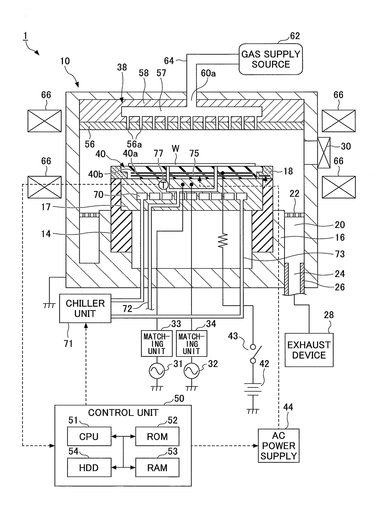
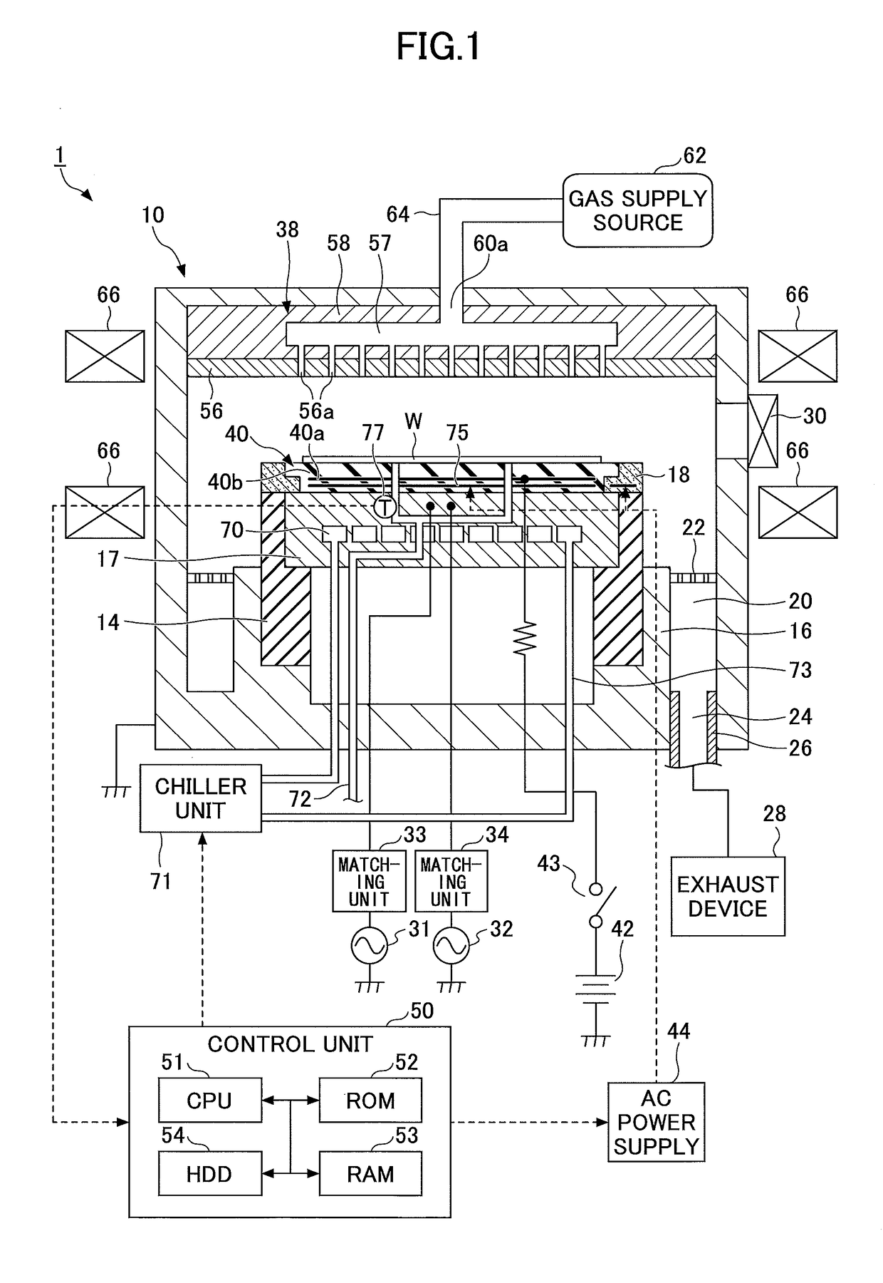
[0020]First, the overall configuration of an etching apparatus 1 according to an embodiment of the present invention will be described. FIG. 1 is a cross-sectional view of the etching apparatus 1 according to the present embodiment.

[0021]The etching apparatus 1 includes a cylindrical processing chamber 10 made of aluminum having an alumite-treated (anodized) surface, for example. The processing chamber 10 is grounded.

[0022]A mounting table 17 is arranged within the processing chamber 10. The mounting table 17 may be made of aluminum (Al), titanium (Ti), or silicon carbide (SiC), for example, and is s...


PUM


Abstract

An etching method for etching a silicon oxide film is provided that includes generating a plasma from a gas including a hydrogen-containing gas and a fluorine-containing gas using a high frequency power for plasma generation, and etching the silicon oxide film using the generated plasma. The fluorine-containing gas includes a hydrofluorocarbon gas, and the sticking coefficient of radicals generated from the hydrofluorocarbon gas is higher than the sticking coefficient of radicals generated from carbon tetrafluoride (CF4).

Description

CROSS-REFERENCE TO RELATED APPLICATION[0001]The present application is based on and claims the benefit of priority to Japanese Patent Application No. 2015-250060 filed on Dec. 22, 2015, the entire contents of which are hereby incorporated by reference.BACKGROUND OF THE INVENTION[0002]1. Field of the Invention[0003]The present invention relates to an etching method.[0004]2. Description of the Related Art[0005]Etching methods for etching a silicon oxide film using an etching gas including CH2F2 gas at low temperatures are known (e.g., see Japanese Unexamined Patent Publication No. 2015-159308). Japanese Unexamined Patent Publication No. 2015-159308 describes an etching gas for forming a contact hole pattern having a high aspect ratio.[0006]Also, an etching method is known that involves exciting a gas containing hydrogen gas, hydrogen bromide gas, nitrogen trifluoride gas, and at least one of hydrocarbon gas, fluorocarbon gas, and hydrofluorocarbon gas, and etching a multilayer film in...

Claims


Application Information

Patent Timeline
Patent Type & Authority Applications(United States)
IPC IPC(8): H01L21/311H01J37/32H01L21/3065
CPCH01L21/31116H01L21/31144H01J2237/334H01J37/32009H01L21/3065H01J37/32082H01J37/32137H01J2237/3343H01J37/32165H01L21/02315H01L21/67069H05H1/46H01J49/105H01L21/324H01L2924/01009
Inventor TAKASHIMA, RYUICHIGOHIRA, TAKUOOYA, YOSHINOBU
Owner TOKYO ELECTRON LTD
Why Eureka
Try Eureka