Photometer/nephelometer device and method of using to determine proppant concentration

a technology of proppant concentration and photometer, which is applied in the direction of porous material analysis, porous material analysis, and well accessories, etc., can solve the problems of poor placement of proppant, limited proppant transport, and fractures of propagate in the reservoir matrix

Inactive Publication Date: 2017-07-27
PRAXAIR TECH INC
View PDF0 Cites 18 Cited by
  • Summary
  • Abstract
  • Description
  • Claims
  • Application Information

AI Technical Summary

Benefits of technology

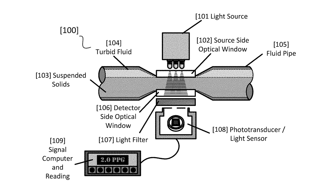
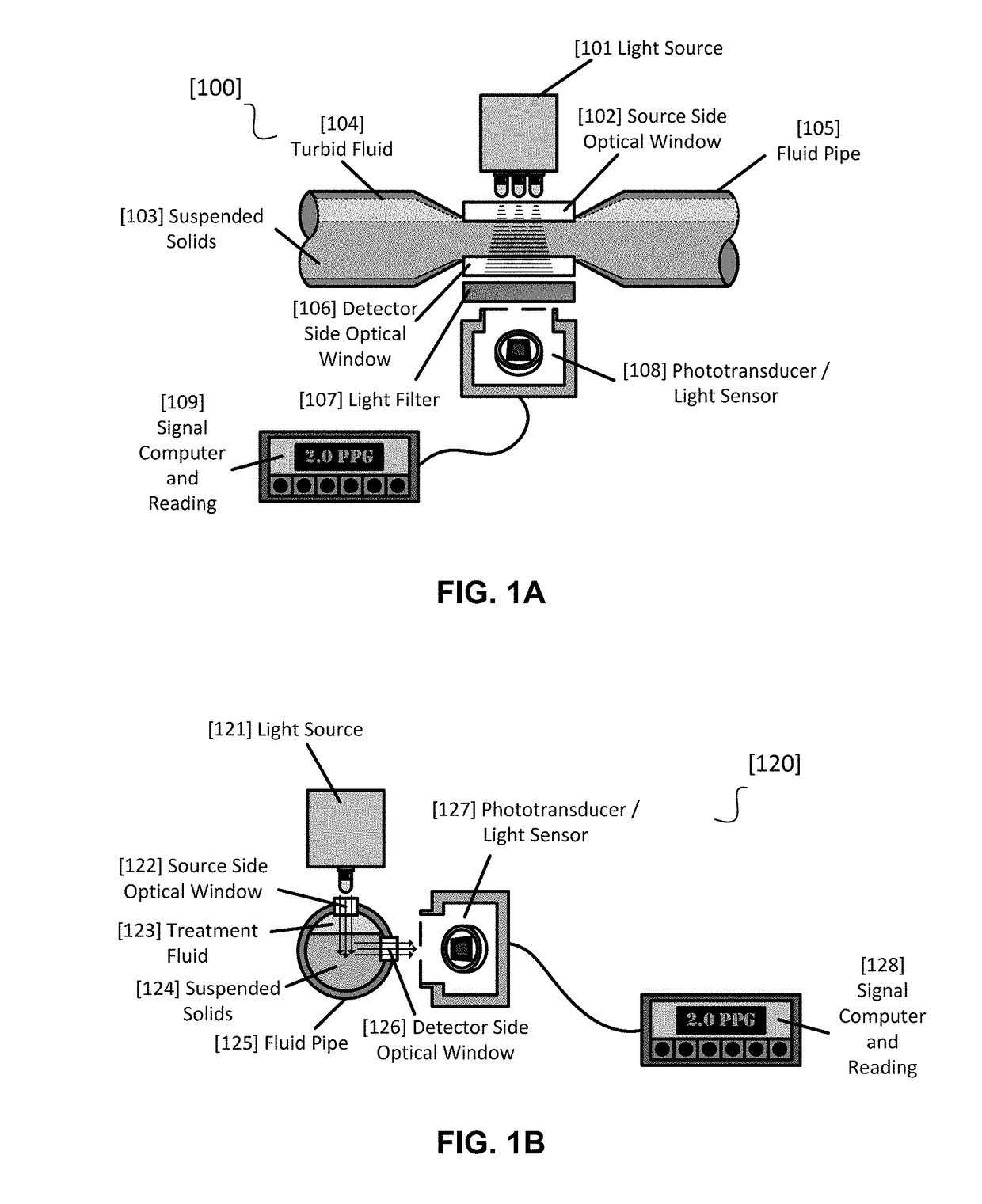
[0016]The present invention provides an optical device to measure the concentration of proppant concentration in a fracturing fluid, wherein the carrier fluid is preferably liquid carbon dioxide. More specifically, this system employs an instrument that uses near-infrared, visible, or ultra-violet light for detection, measurement, and control of proppant in a pressurized flowing fracturing fluid stream by the attenuation (by absorption and scattering) or scattering of light.
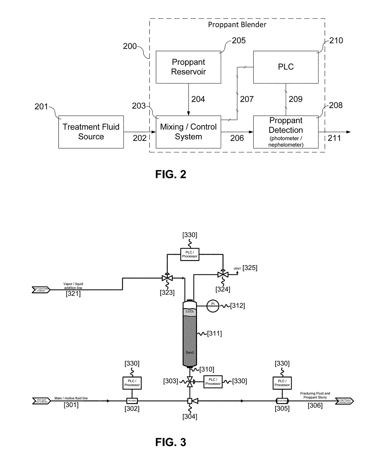
[0017]In one aspect of the invention, a feedback control method for adjusting the proppant concentration in a fracturing fluid that is utilized in stimulation of an underground formation is provided. The method includes supplying proppant or proppant slurry from proppant reservoir to a fluid stream; combining the proppant or proppant slurry with the fluid forming a fracturing fluid containing proppant and measuring the concentration of the proppant in said fracturing fluid downstream by a concentration meter, wherein the concentration meter is photometer/nephelometer device utilizing optical light; providing a feedback signal to a computer; and changing the concentration of the fracturing fluid based on the feedback signal of the concentration meter.
[0018]In another aspect of the invention, a feedback

Problems solved by technology

As these pressure forces increase, they commence and propagate fractures (fissures or cracks) in the reservoir matrix.
For low viscosity fluids like CO2, proppant transport is limited, in one respect, due to the lack of additive systems available that may enhance viscosity and improve the proppant carrying capacity of the fluid.
However, with a predominantly LCO2 fracturing fluid, a major drawback exists because of the less than optimal proppant transport characteristics of this fluid resulting in poor placement of proppant.
These

Method used


Image

  • Photometer/nephelometer device and method of using to determine proppant concentration
  • Photometer/nephelometer device and method of using to determine proppant concentration
  • Photometer/nephelometer device and method of using to determine proppant concentration

Examples


example

[0033]To demonstrate the efficacy for ultra-light weight proppant detection with NIR photometry, a laboratory experiment was set up using NIR emmiting LED's, a NIR sensitive phototransducer, and vials of suspended plastic ULW proppant. The vials contained various concentrations of ULWP from 0 to 1 ppa (or ˜2.5 ppa sand equivalent) with water as a suspension fluid. Specifically, four vials at concentrations of 0, 0.25, 0.5, and 1.0 ppa were prepared. The ULW proppant tested was a thermoplastic developed by Sun Drilling under the trade name FracBlack HT. The material has a specific gravity close to that of water and CO2, ˜1.054 or 8.8 lbs / gal.

[0034]A 850 nm monochromatic, NIR-emitting LED was selected to minimize the light interactions with the water in the vials. The transmission and scattering of light was measured using current generated from a photodiode. The current was measured with resistor shunt and voltmeter.

[0035]A vial of proppant free water (0 ppa) was used to calibrate re...


PUM


Abstract

A system is described that provides for the measurement and control of proppant concentration in a liquefied gas fluid stream utilizing a non-nuclear optical detection device such as a near-infrared (NIR), visible (Vis), and ultraviolet (UV) photometer/nephelometer to be used in the fracture treatment of subterranean hydrocarbon formations.

Description

FIELD OF INVENTION[0001]The present invention relates to a control system and method utilizing a non-nuclear optical detection device such as a near-infrared (NIR), visible (Vis), and ultraviolet (UV) photometer to regulate the flow of proppant into a fracture treatment fluid stream.BACKGROUND OF THE INVENTION[0002]Hydraulic fracturing as utilized herein refers to a process whereby a fluid is pumped into a well bore communicating with a subterranean reservoir under sufficient pressure to fracture the matrix of the subterranean geological formation. As these pressure forces increase, they commence and propagate fractures (fissures or cracks) in the reservoir matrix. The dimensions of the fractures generally increase by continuing to pump the pressurized fluid into the formation through the well bore.[0003]Proppant is typically added to prop the fractures open and facilitate oil and gas recovery from the well after the treatment has been completed. The materials generally comprise of ...

Claims


Application Information

Patent Timeline
IPC IPC(8): G01N15/06E21B43/267E21B43/26G01N21/53
CPCG01N15/06G01N21/53G01N2015/0693E21B43/26E21B43/267G01N21/85E21B43/2607
Inventor SCHARMACH, WILLIAM J.
Owner PRAXAIR TECH INC
Why Eureka
Try Eureka