Medical Implant Porous Scaffold Structure Having Low Modulus

Inactive Publication Date: 2017-08-10
FUJIAN INST OF RES ON THE STRUCTURE OF MATTER CHINESE ACAD OF SCI
View PDF46 Cites 1 Cited by
  • Summary
  • Abstract
  • Description
  • Claims
  • Application Information

AI Technical Summary

Problems solved by technology

However, the autologous bone transplantation may cause donor site pain and has limited sources, the allogenic bone transplantation has the possibility of immune reaction and viral infection, the bioceramic has intrinsic brittleness, the organic polymer has a too low strength, and the degradable materials are still in the stage of laboratory research.
Accordingly, neither of these materials has not been widely used in the treatment and repair of the load-bearing bone.
At this time, the bone tissue surrounding the metal implants will withstand a low-load state for a long term, leading to osteoporosis caused by bone resorption, in which case the implant would easily loose, and the bone tissue is prone to fracture under stress.
Currently, the “stress shielding effect” as an important reason for shortening the service time of the metal implant, can invisibly increase the replacement frequency of the implants of the patients, and meanwhile aggravate t

Method used


Image

  • Medical Implant Porous Scaffold Structure Having Low Modulus
  • Medical Implant Porous Scaffold Structure Having Low Modulus
  • Medical Implant Porous Scaffold Structure Having Low Modulus

Examples


example 1

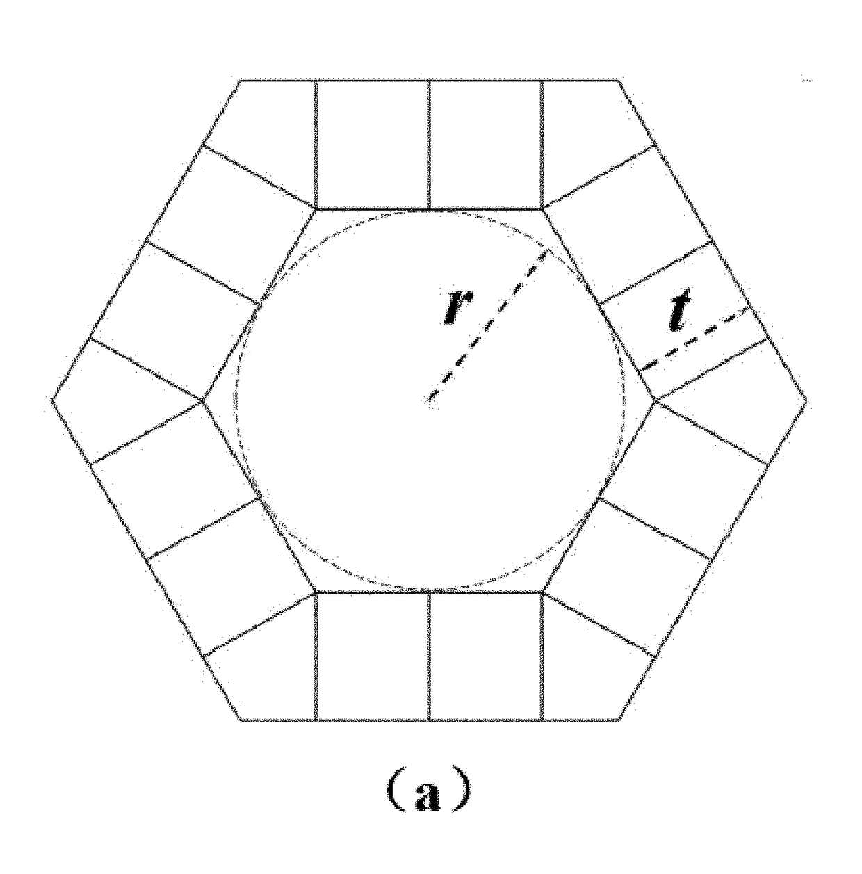
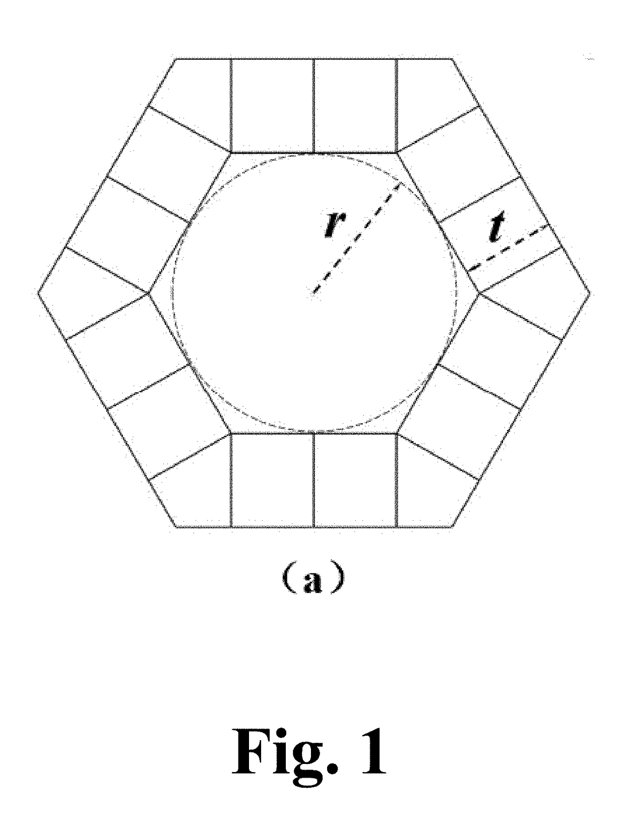
[0065]For the basic unit of the hexagonal prism, when α-Ti (E=110 GPa, v=0.33) was selected as the implant materials, as shown in FIG. 3, the finite element method can be used to calculate the relationship between the relative modulus of the scaffold materials and the relative density of the scaffold. The result showed that when η1 was selected to range from 1.0 to 2.5, η2 was selected to range from 0.10 to 0.50, and the inscribed circle radius r of the interconnected pore was selected to range from 150 μm to 750 μm, the relative modulus of the scaffold materials could be less than 30 GPa, meeting the modulus range of human cortical bone.

example 2

[0066]For the basic unit of the quadrangular prism, when α-Ti (E=110 GPa, v=0.33) was selected as the implant materials, as shown in FIG. 4, the finite element method can be used to calculate the relationship between the relative modulus of the scaffold materials and the relative density of the scaffold. The result showed that when η1 was selected to range from 1.0 to 2.5, η2 was selected to range from 0.1 to 0.35, and the inscribed circle radius r of the interconnected pore was selected to range from 150 μm to 750 μm, the relative modulus of the scaffold materials could be less than 30 GPa, meeting the modulus range of human cortical bone.

[0067]Mg Example Group

example 3

[0068]For the basic unit of the hexagonal prism, when Mg (E=44 GPa, v=0.26) was selected as the implant materials, as shown in FIG. 3, the finite element method can be used to calculate the relationship between the relative modulus of the scaffold materials and the relative density of the scaffold. The result showed that when η1 was selected to range from 1 to 2.5, η2 was selected to range from 0.1 to 0.5, and the inscribed circle radius r of the interconnected pore was selected to range from 150 μm to 750 μm, the relative modulus of the scaffold materials could be less than 30 GPa, meeting the modulus range of human cortical bone.


PUM


Abstract

A medical implant porous scaffold structure having low modulus, wherein said structure is formed by multiple basic units superposed sequentially along the three-dimensional directions in three-dimensional space, each of the basic units is composed of a quadrangular prism or hexagonal prism having central interconnected pores encircled by four or six side walls, each of the side walls is composed by a “X-type” frame structure formed by two crossed ribs, and the central interconnected pores of the adjacent basic units arranged along the axis direction of the quadrangular prism or the hexagonal prism are interconnected to each other. The structure could not only reduce the modulus of the implant, make the modulus of the implant and strength achieve an ideal match, improve the configuration of traditional metal implants to optimize the distribution of mechanical and weaken the stress shielding effect; but also has a regular interconnected pores structure which is conducive to bone tissue in-growth, and can increase mutual locking of bone tissue and implant and shorten the recovery time of patients.

Description

TECHNICAL FIELD[0001]The present disclosure relates to a porous scaffold structure, particularly to a medical implant porous scaffold structure having low modulus, belonging to the field of medical implant materials.BACKGROUND OF THE INVENTION[0002]In the field of the treatment and repair of bone diseases such as bone fracture or bone necrosis, particularly in the treatment and repair of the load-bearing bone, surgery, in which a dead bone is replaced with an implant, is a common and useful way to prevent bone diseases from further deteriorating and to avoid late fractures and even disability. So far, common implants mainly include autologous bone, allogenic bone, bioceramic, organic polymer, degradable materials, metal materials and so on. However, the autologous bone transplantation may cause donor site pain and has limited sources, the allogenic bone transplantation has the possibility of immune reaction and viral infection, the bioceramic has intrinsic brittleness, the organic p...

Claims


Application Information

Patent Timeline
IPC IPC(8): A61F2/28A61L27/06A61L27/04A61L27/12
CPCA61F2/28A61F2310/00011A61L27/06A61L27/047A61L27/045A61L27/042A61L27/04A61F2002/2835A61F2310/00293A61F2310/00137A61F2310/00131A61F2310/00101A61F2310/00089A61F2310/00059A61F2310/00041A61F2310/00035A61F2310/00029A61F2310/00023A61F2310/00017A61L27/12A61L27/56A61L2430/02A61L27/50A61F2/3094A61F2002/30985A61F2002/30943
Inventor LIN, JINXINWU, SONGQUANLIN, JUNJIELU, YANJINGAN, YILIANGZHAO, CHAOQIAN
Owner FUJIAN INST OF RES ON THE STRUCTURE OF MATTER CHINESE ACAD OF SCI
Why Eureka
Try Eureka