System And Method For Characterizing Particulates in a Fluid Sample

a fluid sample and particulate technology, applied in the field of system and method for characterizing particulates in fluid samples, can solve the problems of high vacuum conditions, high cost of electron microscopy, and inability to routinely and rapidly identify instruments, and achieve the effect of low surface roughness

Active Publication Date: 2017-08-24
OPTOFLUIDICS
View PDF5 Cites 37 Cited by
  • Summary
  • Abstract
  • Description
  • Claims
  • Application Information

AI Technical Summary

Benefits of technology

[0008]In one embodiment, a system for characterizing at least one particle from a fluid sample includes a filter disposed upstream of an outlet; a luminaire configured to illuminate the at least one particle at an oblique angle; and an imaging device configured to capture and process images of the illuminated at least one particle as it rests on the filter for characterizing the at least one particle. In one embodiment, the system includes a luminaire configured to illuminate the at least one particle at an angle coplanar with a flat plane of the filter. In one embodiment, the luminaire comprises a plurality of illuminating devices. In one embodiment, the plurality of illuminating devices are disposed radially around and directed inwardly towards the filter. In one embodiment, the illuminating devices are LEDs. In one embodiment, the system includes a luminaire configured to illuminate the at least one particle by bright field illumination. In one embodiment, the imaging system is configured to generate a composite image comprising oblique angle illumination and bright field illumination. In one embodiment, the imaging system is configured to characterize a plurality of particles based on a combination of oblique angle illumination and bright field illumination. In one embodiment, a well plate having a plurality of wells that each terminate on a filter. In one embodiment, the filter is a membrane. In one embodiment, the membrane is black. In one embodiment, the surface has a low surface roughness. In one embodiment, the well plate comprises a transparent material. In one embodiment, the well plate comprises a transparent material with an opaque layer on the top surface. In one embodiment, the well plate comprises a reflective film. In one embodiment, the well plate comprises an opaque bright white material. In one embodiment, the plurality of wells have a decreasing radius moving towards the filter. In one embodiment, the system includes a vacuum manifold connected to a negative pressure source and configured for fluid communication with the plurality of wells. In one embodiment, the well plate comprises an optical feature comprising at least one of a mirror, lens and prism. In one embodiment, the imaging device is configured to characterize and identify a material type of the at least one particle using a machine learning algorithm. In

Problems solved by technology

There are existing tools that can provide particle counts and size in the FDA regulated size range, however there is no instrumentation that can routinely and rapidly identify what the particles are actually made of (see e.g. Bee J S, Goletz T J, Ragheb J A. The future of protein particle characterization and understanding its potential to diminish the immunogenicity of biopharmaceuticals: a shared perspective.
In general, they are not routine measurement instruments and are only used occasionally due to low throughput and the complexity of sample prep.
Electron microscopy is expensive, requires complicated sample prep, highly trained operators and high vacuum conditions.
Fluorescence microscopy requires staining of the particles which is undesirable.
In the protein therapeutic space, any changes to the sample, including dilution temperature change, additional reagents added can disrupt the delicate balance of the carefully formulated sample.
There is always a fear that the changes to the sample will affect the measurement,

Method used


Image

  • System And Method For Characterizing Particulates in a Fluid Sample
  • System And Method For Characterizing Particulates in a Fluid Sample
  • System And Method For Characterizing Particulates in a Fluid Sample

Examples


experimental examples

[0087]The invention is now described with reference to the following Examples. These Examples are provided for the purpose of illustration only and the invention should in no way be construed as being limited to these Examples, but rather should be construed to encompass any and all variations which become evident as a result of the teaching provided herein.

[0088]Without further description, it is believed that one of ordinary skill in the art can, using the preceding description and the following illustrative examples, make and utilize the present invention and practice the claimed methods. The following working examples therefore, specifically point out the preferred embodiments of the present invention, and are not to be construed as limiting in any way the remainder of the disclosure.

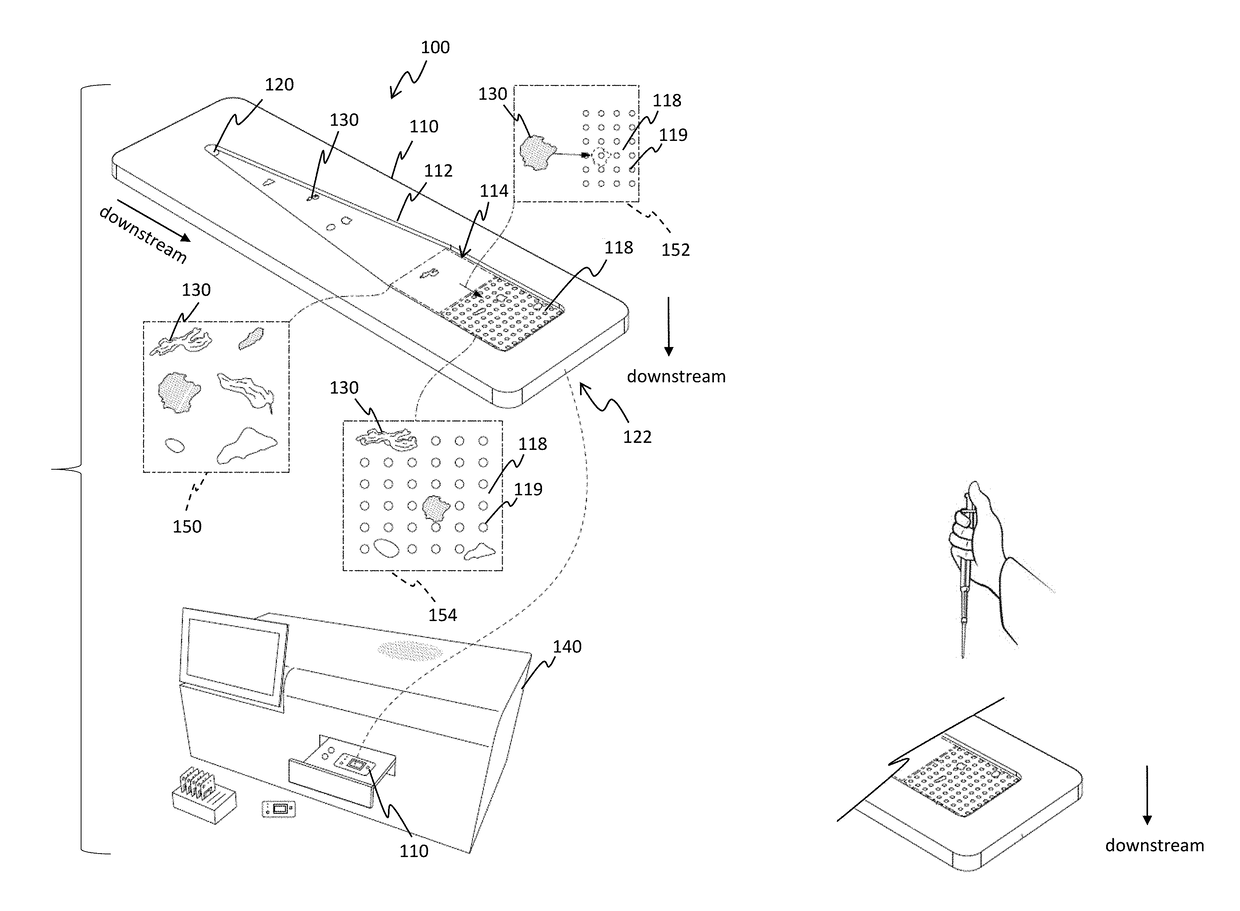
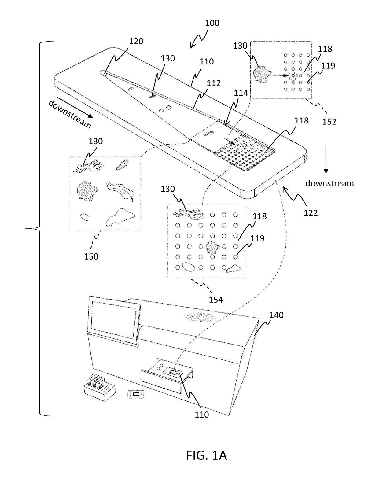
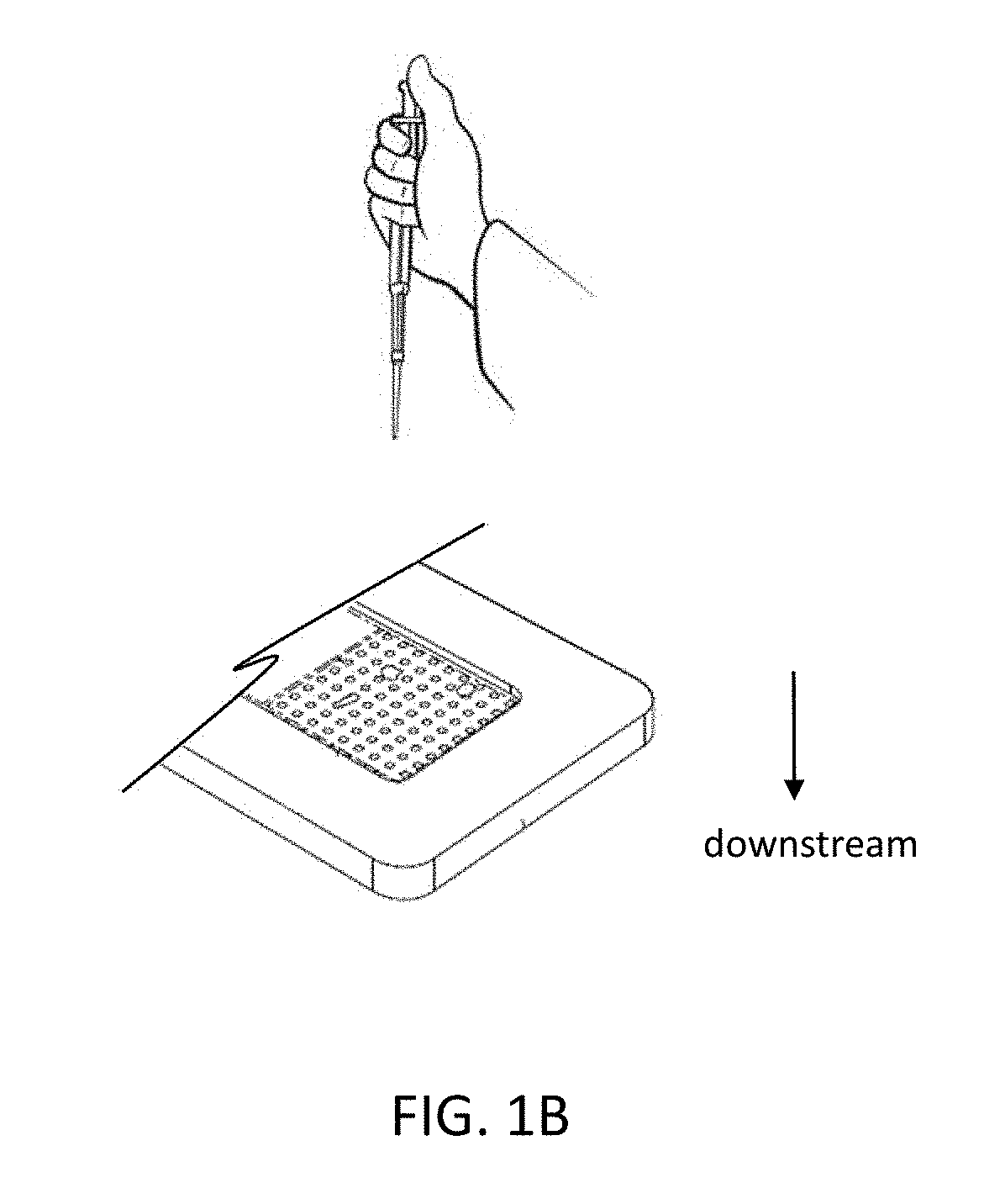
[0089]In certain embodiments, 3D printed flow cells are used to hold and perform experiments on the electroformed micro-meshes in isolation (without microflow imaging). In other embodiments, a flow ...


PUM


Abstract

A system for characterizing at least one particle from a fluid sample is disclosed. The system includes a filter disposed upstream of an outlet, and a luminaire configured to illuminate the at least one particle at an oblique angle. An imaging device is configured to capture and process images of the illuminated at least one particle as it rests on the filter for characterizing the at least one particle. A system for characterizing at least one particle using bright field illumination is also disclosed. A method for characterizing particulates in a fluid sample using at least one of oblique angle and bright field illumination is also disclosed.

Description

CROSS-REFERENCE TO RELATED APPLICATIONS[0001]This application claims priority to U.S. Provisional Patent Application No. 62 / 360,832, filed Jul. 11, 2016, and U.S. Provisional Patent Application No. 62 / 296,701, filed Feb. 18, 2016, both of which are incorporated herein by reference in their entireties.BACKGROUND OF THE INVENTION[0002]Protein therapeutics have grown dramatically over the past 25 years and now comprise 15-30% of the pharmaceutical market. The primary quality concern for this class of therapeutics is that they can elicit an immune response from patients who develop anti-drug antibodies. High levels of anti-drug antibodies can eliminate therapeutic effects by clearing the drug from the body. This immune response affects 1-10% of patients, who must stop taking the medication and will return to their initial diseased state. The presence of particulate matter in these therapeutics (e.g. shed glass from a syringe or a protein aggregate) enhances this immune response and the ...

Claims


Application Information

Patent Timeline
IPC IPC(8): G02B21/36G02B21/16G02B21/12G01N21/64G01N15/14
CPCG02B21/367G01N21/6456G01N15/1463G01N2201/062G02B21/12G02B21/16G01N2015/0065G01N15/1436G01N15/1429G01N2015/0053G01N2015/0011G01N2015/003G01N15/0227G01N15/0272G01N15/1425G01N21/6452G01N21/65G02B21/24G01N2015/0294G01N2015/1006G01N2015/1493G01N2015/1497G01N2021/3595G01N15/1434G01N15/147G01N15/1475
Inventor ASHCROFT, COLBYDIPAOLO, BRIANKONICA, GJERGJICASTNER, THOMASCORDOVEZ, BERNARDOEARHART, CHRISTOPHERERICKSON, DAVIDHART, ROBERT
Owner OPTOFLUIDICS
Why Eureka
Try Eureka