Automated optical metrology computer aided inspection station and method of operation

a computer-aided inspection and metrology technology, applied in the field of 3d optical metrology, can solve the problems of reducing the accuracy and usefulness of scan data, reducing the efficiency of computer-aided inspection, and labor-intensive and time-consuming 3d scanning, etc., and achieves faster inspection, greater throughput, and faster understanding

Inactive Publication Date: 2017-08-31
LEVEL 3 INSPECTION
View PDF2 Cites 44 Cited by
  • Summary
  • Abstract
  • Description
  • Claims
  • Application Information

AI Technical Summary

Benefits of technology

[0015]In addition to the primary benefits of measurement accuracy and comprehensiveness that Optical Scanning & Computer Aided Inspection technologies and processes provide, additional advantages are: faster inspection; greater throughput, faster understanding from 3D visualization, easier disposition, more confident decision support; user/operator readiness; manufacturing shop-floor applicability; receiving inspection applicability, completely digital results that are trendable, trackable, traceable au

Problems solved by technology

Computer Aided Inspection (CAI) from high-accuracy 3D Scanning (3DS) is a labor-intensive and time-consuming activity to perform, especially for complex parts.
Moving the scanner manually from location to location around the part in order to address all of the part surfaces for visual access and digitizing is a slow and methodical operation.
These

Method used


Image

  • Automated optical metrology computer aided inspection station and method of operation
  • Automated optical metrology computer aided inspection station and method of operation
  • Automated optical metrology computer aided inspection station and method of operation

Examples


Embodiment Construction

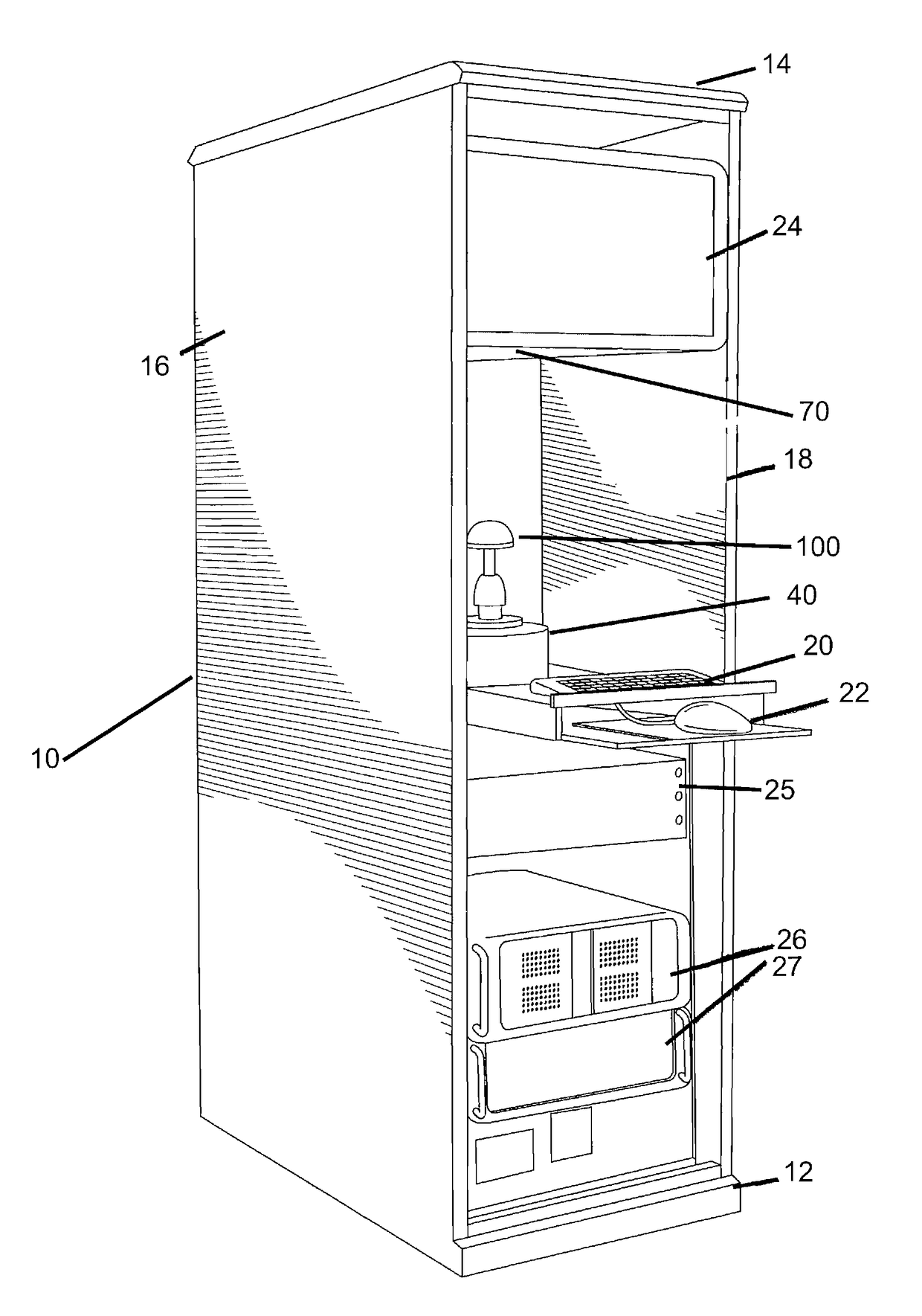
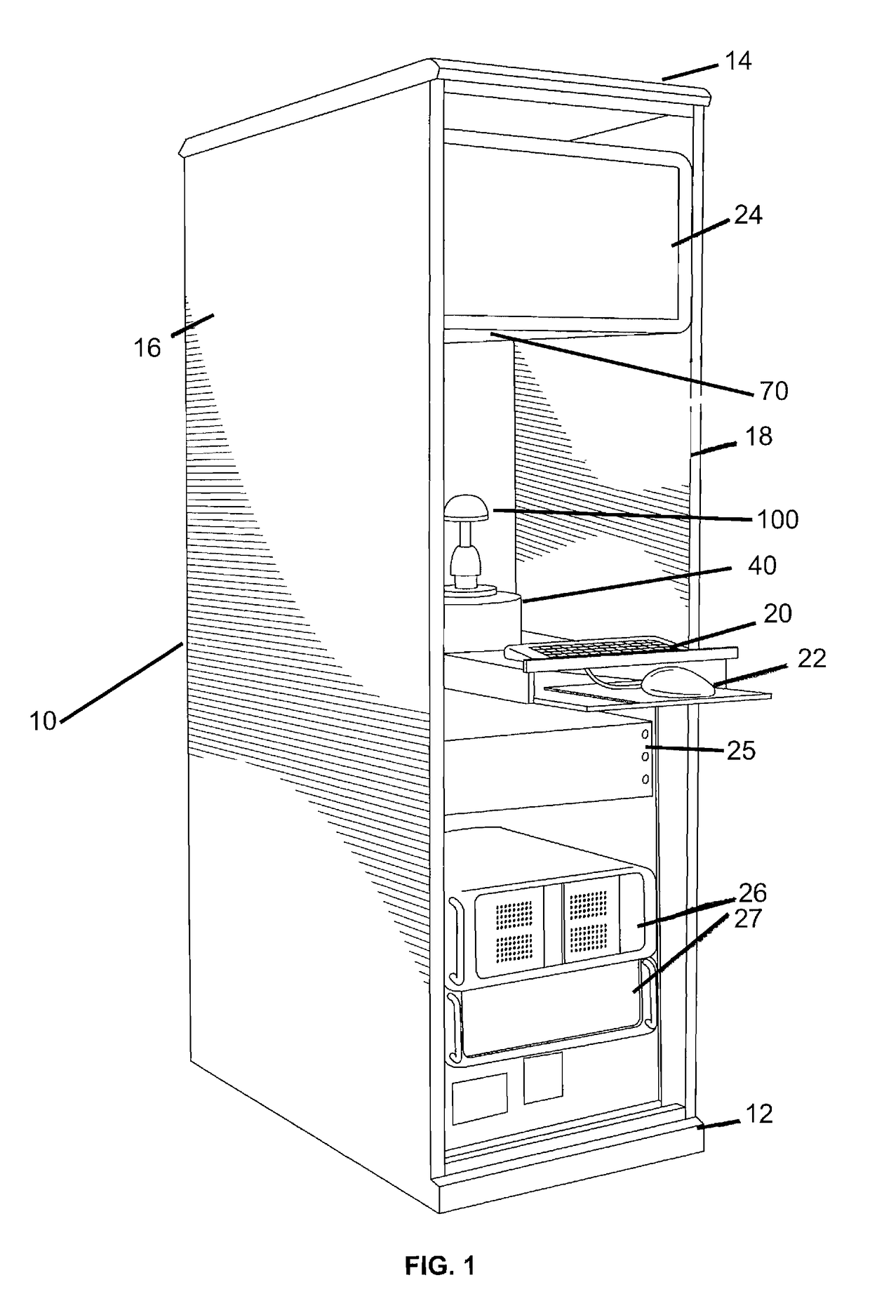
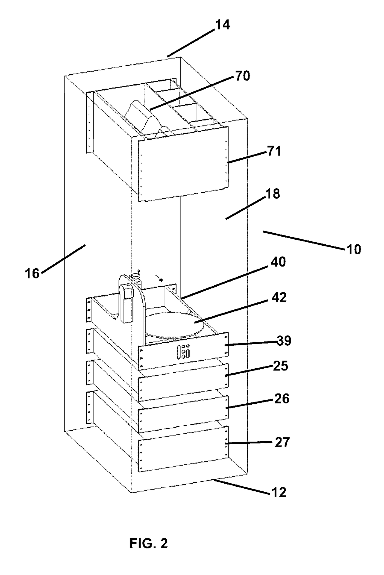
[0026]The invention is an integrated, automated Optical Metrology 3D Scanner, Parts Presenter, and Computer Aided Inspection system that receives a part and rapidly performs all of the process steps required to create the desired inspection outcome determination with high levels of trendable, traceable, trackable results reporting for part disposition, process optimization, quality control, production stage monitoring, and Statistical Process Control, among other benefits, all with minimal non-technical operator effort beyond inserting the part(s) to be inspected and selecting by bar-code scanning a label to launch the automated routine, or simply hitting ‘Start’. This inspection part insertion can also readily be automated with robotics to completely eliminate human operators.

[0027]This invention consists of the following components (among other additions):[0028]1. One or multiple 3D Scanner(s) with structured-light pattern source, projector and camera that produces 3D Scan files, ...


PUM


Abstract

An automated 3D Optical Metrology Scanning and Computer Aided Inspection System for dimensional inspection of precision manufactured parts. The system example and implemented configuration is based within a relocatable cabinet providing ambient light and optional temperature control. The cabinet further includes a part placement area having an optical metrology scanner positioned over a multi-axis robotic arm positioned in the part placement area. The robotic arm is constructed and arranged to grip and manipulate parts within a field of view of the optical metrology scanner. The robotic arm provides adequate multi-axis control to rotate and tilt and translate tp manipulate the part to allow substantially every surface of the part to be scanned. Dimensional comparison and analysis software application provide geometric conformance/deviation plus extraction of the dimensions indicated in the part computer aided design (CAD) model.

Description

CROSS REFERENCE TO RELATED APPLICATIONS[0001]In accordance with 37 C.F.R. §1.76, a claim of priority is included in an Application Data Sheet filed concurrently herewith. Accordingly, the present invention claims priority as a continuation-in-part of U.S. patent application Ser. No. 13 / 467,546, filed May 9, 2012, entitled “Portable Optical Metrology Inspection Station and Method of Operation”, which claims priority to U.S. Provisional Patent Application No. 61 / 484,016, filed May 9, 2011, entitled “Portable White Light Scanning Inspection Station and Method of Operation”, the entire contents of which are hereby expressly incorporated by reference.FIELD OF THE INVENTION[0002]The invention is directed to the field of 3D Optical Metrology, including White Light Scanning and Blue Light Scanning, or other structured light scanning for part digitization, and in particular to an integrated, automated 3D Optical Scanning and Computer Aided Inspection System for faster dimensional inspection ...

Claims


Application Information

Patent Timeline
IPC IPC(8): G06T7/00G01N21/88G05B19/4097G06F17/30G05B19/406G01B11/02H04N13/02
CPCG06T7/001G01B11/02G01N21/8851H04N13/0203G05B2219/37441G05B19/406G05B19/4097G05B2219/35134G05B2219/35189G06F17/3028G01B21/047G01B11/24H04N13/204G06F16/51Y02P90/02
Inventor GREENE, WILLIAM J.MCAFEE, SCOTT T.
Owner LEVEL 3 INSPECTION
Why Eureka
Try Eureka