Photo-Activatable Gel Coated Intracranial Stent and Embolic Coil

a technology of photoactivation gel and intracranial stent, which is applied in the field of stents and embolic devices, can solve the problems of complete or partial occlusion of the aneurysm cavity, and achieve the effect of effectively preventing the contact of x-ray photons and preventing premature activation of gel

Active Publication Date: 2017-09-21
THOMAS JEFFREY E
View PDF8 Cites 57 Cited by
  • Summary
  • Abstract
  • Description
  • Claims
  • Application Information

AI Technical Summary

Benefits of technology

[0008]The stent delivery system described and claimed below incorporate the necessary structural modifications and features needed to provide the desired handling characteristic of an intracranial stent or coil delivery system. For the most part, they are designed with a radially expanding stent in mind, but they will prove useful in applications of balloon expanding or shape memor

Problems solved by technology

The transformation may also be chemical and accompanied with release of heat or photochemical to become a tissue irritant o

Method used


Image

  • Photo-Activatable Gel Coated Intracranial Stent and Embolic Coil
  • Photo-Activatable Gel Coated Intracranial Stent and Embolic Coil
  • Photo-Activatable Gel Coated Intracranial Stent and Embolic Coil

Examples


##ic example 1

Prophetic Example 1

Treating a Wide-Necked Cerebral Aneurysm

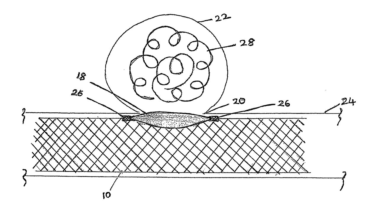
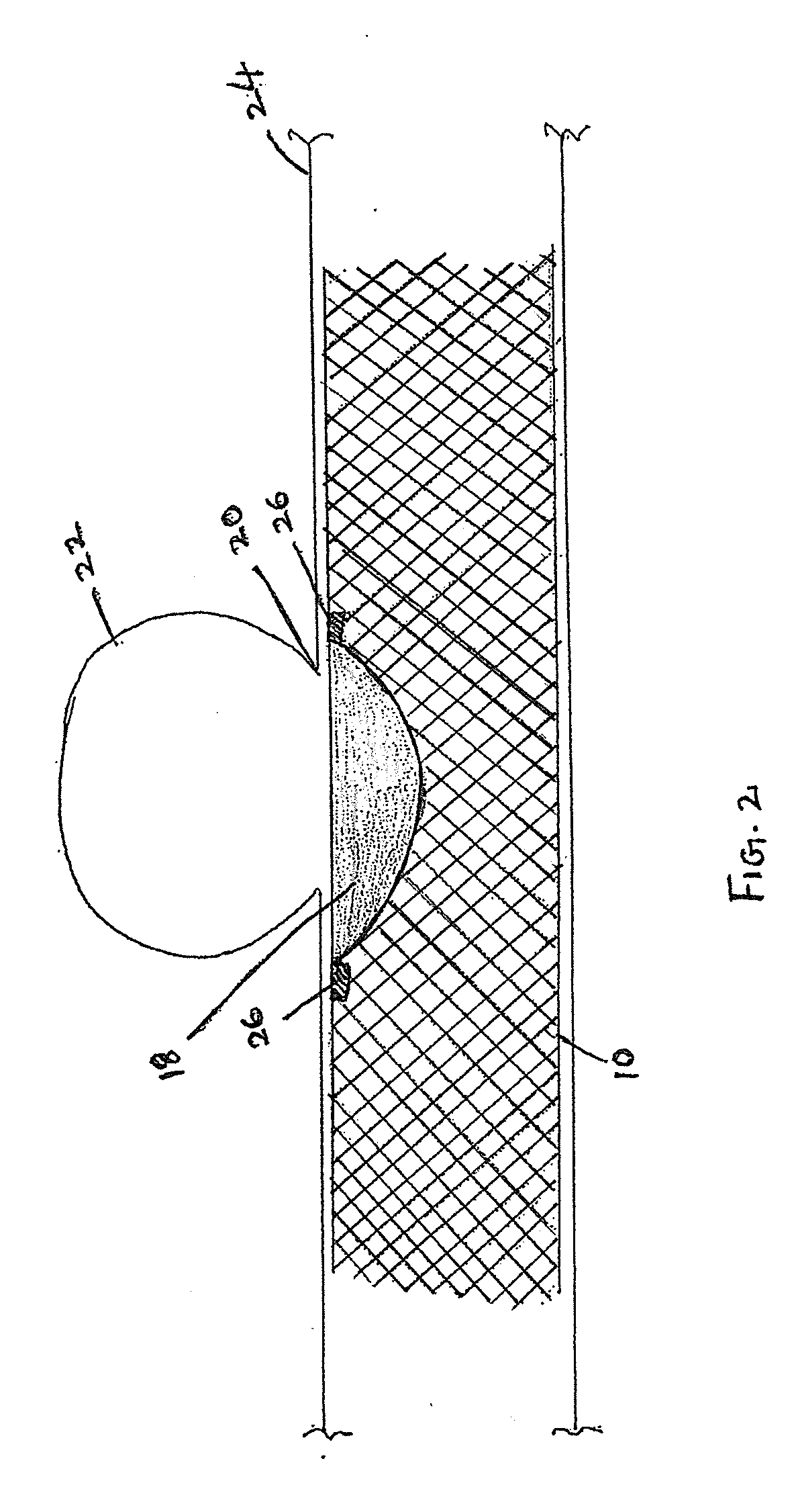
[0024]A patient presents to medical attention with a diagnosis of incidentally-discovered cerebral aneurysm of the internal carotid artery. The patient's angiogram demonstrates that the aneurysm has a wide neck, or orifice, to the parent vessel; therefore it is not amenable to simple coil embolization for fear that coils placed into the aneurysm will prolapse into the parent artery. The patient is also not an ideal candidate for craniotomy and clipping, for other reasons. One option for this patient would be a stent / coil technique, by which coils are deposited into a wide-necked aneurysm through an intracranial stent placed across the aneurysm neck. Although effective, this technique requires two procedures (deployment of intracranial stent, followed by deployment of coils), and this fact automatically doubles the surgical risk of the procedures. Also, being able to cross the stent with a microcatheter after it has been depl...

##ic example 2

Prophetic Example 2

Treating a Site of Arterial Injury

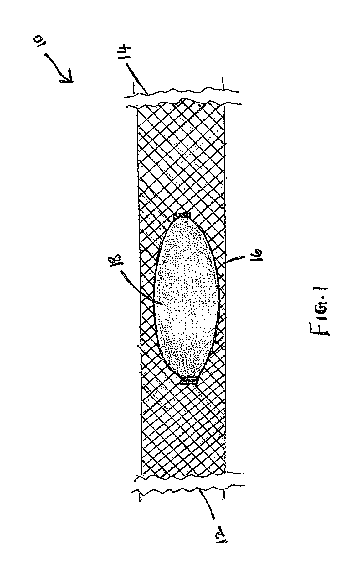
[0027]A dissection is a tear in the arterial wall that allows blood from the lumen of the vessel to enter its muscular wall, expanding and causing stenosis of the residual lumen, or penetrating all layers of the vessel wall, allowing bleeding to occur into the subarachnoid space. A patient in this case arrives at the emergency room with symptoms of headache or stroke. Options for vascular repair include therapeutic occlusion of the involved vessel, direct surgical reconstruction, and endovascular repairs such as stent deployment. For an intracranial dissection, the same problem with navigation exists: a porous flexible reconstructive device is required for navigation of tortuous and fragile cerebral vasculature, but the effectiveness of the device at the target site is compromised by that same flexibility and high porosity that render it inferior. In this case, an effective reconstruction is created by delivering the transformable...


PUM


Abstract

An intracranial stent includes a proximal end, a distal end, and a tubular sidewall extending there between and a patch covering at least a portion of the sidewall; wherein the patch is capable of diverting blood flow past the neck of an intracranial aneurysm. The patch may be made of a photon-activatable material or a tightly woven metal material with a density greater than a density of the sidewall itself.

Description

RELATED APPLICATIONS[0001]This application claims priority to U.S. Provisional Patent Application No. 61 / 991,693 filed May 12, 2014 and titled “Embolic Coil Delivery System and Methods of Using the Same,” U.S. Provisional Patent Application No. 61 / 991,688 filed on May 12, 2014 titled “Photoactivatable Gel Coated Intracranial Stent,” U.S. Provisional Application No. 62 / 058,847 filed on Oct. 2, 2014 titled “Photoactivatable Gel Coated Intracranial Stent and Embolic Coils,” and PCT Patent Application No. PCT / US15 / 30386 filed May 12, 2015 titled “Photo-Activatable Gel Coated Intracranial Stent and Embolic Coil.”FIELD OF INVENTION[0002]The present disclosure generally relates to stents, embolic devices and methods of their use in treating intracranial aneurysms. Specifically, the disclosure relates to an intracranial stent with an outer wall that is at least partially covered with a photon-activatable gel.BACKGROUND OF THE INVENTION[0003]Endovascular treatment of a cerebral aneurysm is c...

Claims


Application Information

Patent Timeline
IPC IPC(8): A61F2/90A61B17/12
CPCA61F2/90A61B17/12031A61B17/12113A61B17/12118A61B17/1214A61F2250/0023A61B2017/00084A61B2017/005A61B2090/3966A61F2002/823A61F2250/0001A61B17/12181A61F2250/0015
Inventor THOMAS, JEFFREY E.
Owner THOMAS JEFFREY E
Why Eureka
Try Eureka