
Magnetic tape and magentic tape device

a magnetic tape and magentic tape technology, applied in the field of magnetic tape and magentic tape devices, can solve the problems of more errors during recording and/or reproduction, difficult for the magnetic head to accurately follow the data track, etc., to achieve the effect of increasing the quantity of information, increasing the recording capacity, and increasing the capacity

Active Publication Date: 2017-09-28
FUJIFILM CORP
View PDF0 Cites 4 Cited by
  • Summary
  • Abstract
  • Description
  • Claims
  • Application Information

AI Technical Summary

Benefits of technology

The patent text is about a way to make magnetic tape with more data capacity. One way to do this is to make the data tracks smaller, which increases the recording density. However, this makes it harder for the magnetic tape to accurately follow the data tracks during recording and reproducing. To address this, the patent proposes the use of head tracking servo that uses servo signals to control the position of the magnetic tape and make it easier for the magnetic head to follow the data tracks. The patent also describes how to make the magnetic layer smoother and improve the positioning precision of the head tracking system. This results in a more precise recording and reproducing of magnetic signals on the tape.

Problems solved by technology

However, when the data track width is reduced, in the process of running a magnetic; tape within a magnetic tape device (drive) for recording and / or reproducing a magnetic signal, variation in the position of the magnetic tape in the widthwise direction makes it difficult for the magnetic head to accurately follow the data track.
This tends to cause more errors to occur during recording and / or reproduction.

Method used

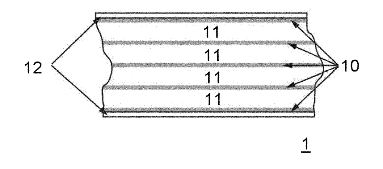
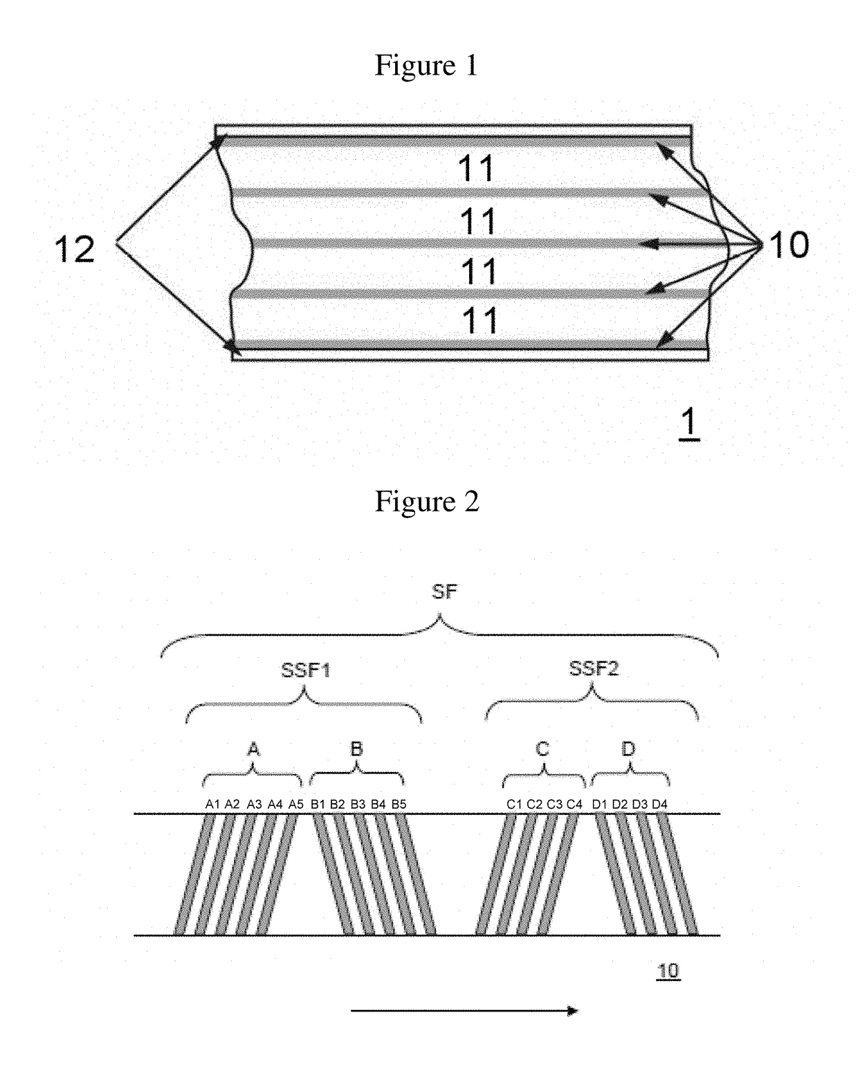
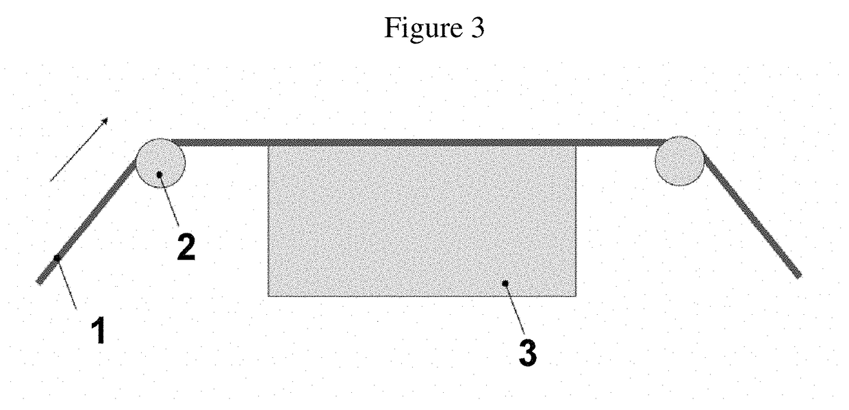

Image

  • Magnetic tape and magentic tape device
  • Magnetic tape and magentic tape device
  • Magnetic tape and magentic tape device

Examples


example 1

(Magnetic Liquid)

[0166]Ferromagnetic hexagonal barium ferrite powder: 100.0 parts (Coercive force He: 2,100 Oe (168 kA / m), average particle size; 25 nm)[0167]Sulfonic acid group-containing polyurethane resin: 15.0 parts[0168]Cyclohexanone: 150.0 parts[0169]Methyl ethyl ketone: 150.0 parts

(Abrasive Liquid)

[0170]α-Alumina (average particle size: 110 nm); 9.0 parts[0171]Vinyl chloride copolymer (MR110 made by Zeon Corp.): 0.7 part[0172]Cyclohexanore: 20.0 parts

(Silica Gel)

[0173]Colloidal silica prepared by the silica gel method (average particles size: 120 nm):3.5 parts[0174]Methyl ethyl ketone: 8.2 parts

(Other Components)

[0175]Butyl stearate: 1.0 part:[0176]Polyisocyanate (Coronate made by Nippon Polyurethane Industry Co., Ltd.): 2.5 parts

(Solvents Added to Finish)

[0177]Cyclohexanone: 180.0 parts[0178]Methyl ethyl ketone: 180.0 parts

[0179][0180]Nonmagnetic inorganic powder (α-iron oxide): 80.0 parts (average particle size: 0.15 μm, average acicular ratio: 7, Brunauer-Emmett-Teller (BE...


PUM

PropertyMeasurementUnit
surface roughness Raaaaaaaaaaa
full width at half maximumaaaaaaaaaa
surface roughness Raaaaaaaaaaa

Abstract

The magnetic tape has a timing base servo pattern on the magnetic layer, wherein the centerline average surface roughness Ra on the surface of the magnetic layer is less than or equal to 1.8 nm, the magnetic layer contains a fatty acid ester, the full width at half maximum of spacing distribution measured by optical interferometry on the surface of the magnetic layer before and after vacuum heating the magnetic tape is greater than 0 nm but less than or equal to 7.0 nm, the difference of spacing measured by optical interferometry on the surface of the magnetic layer after and before vacuum heating the magnetic tape is greater than 0 nm but less than or equal to 8.0 nm.

Description

CROSS-REFERENCE TO RELATED APPLICATIONS[0001]This application claims priority under 35 U.S.C 119 to Japanese Patent Application No. 2016-057866 filed on Mar. 23, 2016. The above application is hereby expressly incorporated by reference, in its entirety.BACKGROUND OF THE INVENTION[0002]Field of the Invention[0003]The present invention relates to a magnetic tape and a magnetic tape device.[0004]Discussion of the Background[0005]Magnetic recording media include tape-shaped media and disk-shaped media. Magnetic recording media in the form of tapes—that is, magnetic tapes—are primarily employed in data storage applications, such as data backup and archives. Information is normally recorded on and reproduced from magnetic tapes by running a magnetic tape in a magnetic tape device (generally called a “drive”) and causing the surface of the magnetic layer of the magnetic tape to come in contact with (slide against) a magnetic head.[0006]Controlling the state in which lubricant is present on...

Claims


Application Information

Patent Timeline
Patent Type & Authority Applications(United States)
IPC IPC(8): G11B20/12G11B5/008
CPCG11B5/00813G11B20/1201G11B5/584
Inventor OZAWA, EIKIKANEKO, TETSUYAKASADA, NORIHITO
Owner FUJIFILM CORP
Learn More