

Process for Partial Upgrading of Heavy Oil
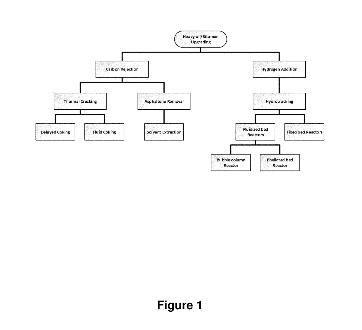
a technology for heavy oil and processing, applied in the field of processing, can solve the problems of heavy oil, extra-heavy oil and bitumen (, heavy oil) cannot be transported by pipeline in a raw state, and the loss of coking and de-asphalting of heavy oil (i.e., carbon rejection) and achieve the effect of reducing viscosity
- Summary
- Abstract
- Description
- Claims
- Application Information
AI Technical Summary
Benefits of technology
Problems solved by technology
Method used
Image

Examples
example 1
[0112]This example shows the effectiveness of the process in the partial upgrading of a sample of Athabascan bitumen. A slurry of 15% (m / m) of fresh goethite (D50<30 μm) and a sample of Athabasca bitumen with 54% (m / m) residue was heated to 450° C. under a fixed hydrogen pressure of 110 bar in a 0.5 liter stirred autoclave. Hydrogen flow was maintained at 1.1 to 1.2 liters per minute. A reflux condenser on top of the reactor returned the condensable hydrocarbons in the vent gas stream back to the reactor, while the non-condensable gases were continuously removed. The residence time of the slurry at the target temperature of 450° C. was 60 minutes. The products were then cooled to room temperature before the reaction vessel was opened. Catalyst particles were separated from the product slurry using vacuum filtration. A sample of the liquid product was characterized by viscosity and density measurements as well as by determination of boiling point distribution using simulated distilla...
example 2
[0114]In order to show the impact of pressure, the test described in Example 1 was repeated with all other conditions unchanged except that the pressure was reduced to 70 bar, as shown in Table 1 (Example 2). Under these conditions about 4% (m / m) coke was formed on the catalyst. The density of the liquid product decreased from about 1010 g / L to about 903 g / L while the measured viscosity was about 7 cSt. The gas yield was about 18% (m / m) of the feed oil, which is higher than that from the test conducted at 110 bar (Example 1). This increase is attributed to gas evolution associated with coking reactions. The conversion of the residue to lighter fractions was about 88% (m / m). More than about 45% of the sulphur in the feed was removed in the form of H2S and iron sulphide.
example 3
[0115]In order to show the impact of temperature, the test described in Example 1 was repeated with all other conditions unchanged, except that the temperature was reduced to 430° C. The results are shown in Table 1 (Example 3). The gas yield was about 7% (m / m) which is lower than for the test conducted at 450° C. The density of liquid product was about 916 g / L compared to about 874 g / L for the liquid produced at 450° C. The conversion of residue to lighter fraction was about 72% (m / m) which is lower than for the test at 450° C., where the conversion was about 91% (m / m). More than about 36% of sulphur in the feed was removed in the form of H2S and iron sulphide.
PUM
 Abstract
Description
Claims
Application Information