
Apparatus for producing organic hydride and method for producing organic hydride using same

Active Publication Date: 2017-11-02
DE NORA PERMELEC LTD +1
View PDF8 Cites 1 Cited by
  • Summary
  • Abstract
  • Description
  • Claims
  • Application Information

AI Technical Summary

Benefits of technology

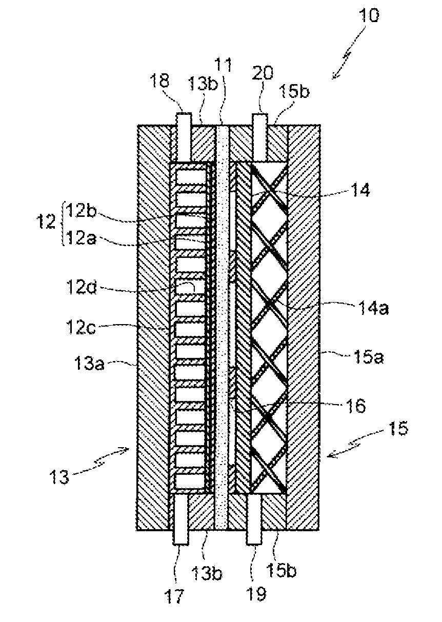
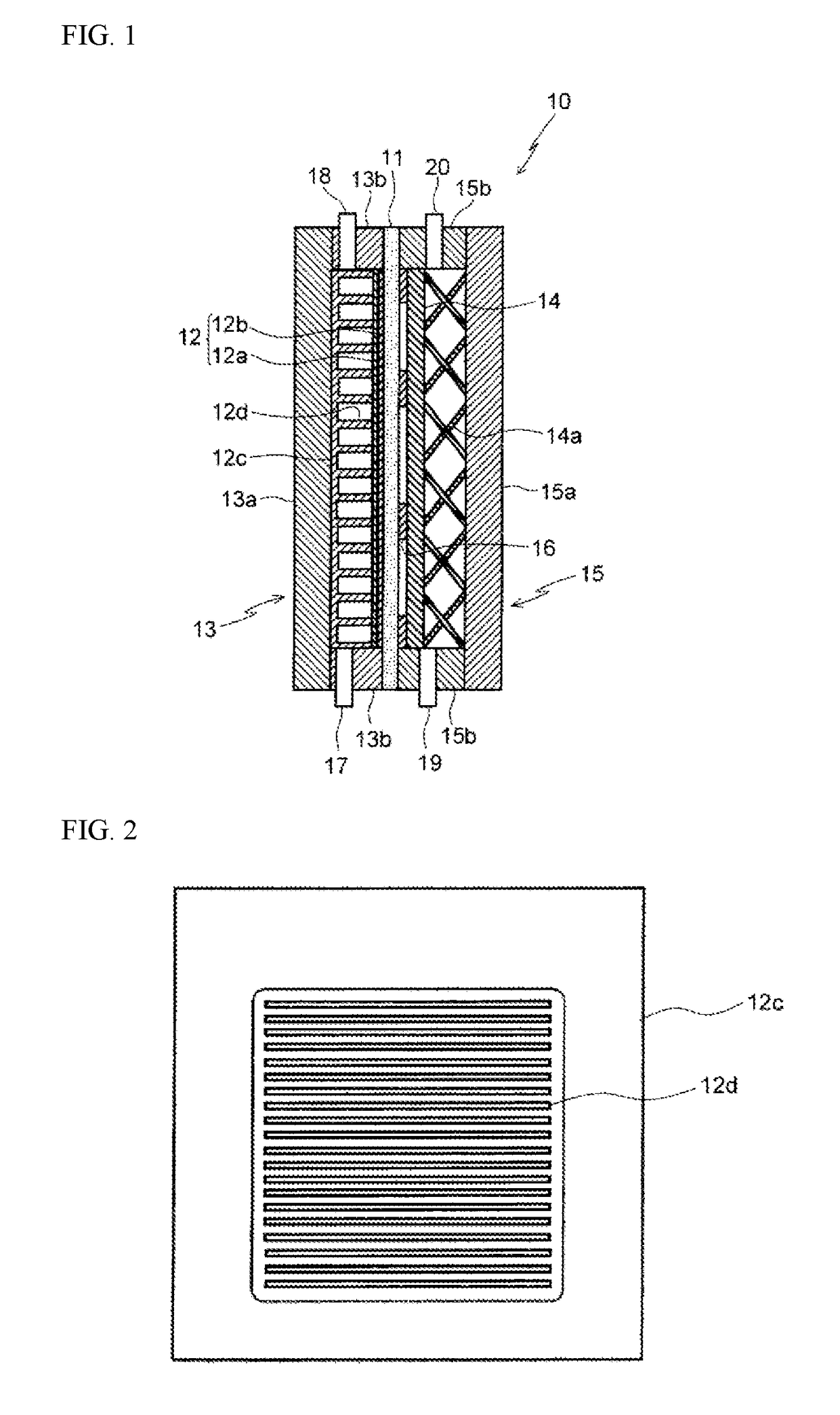
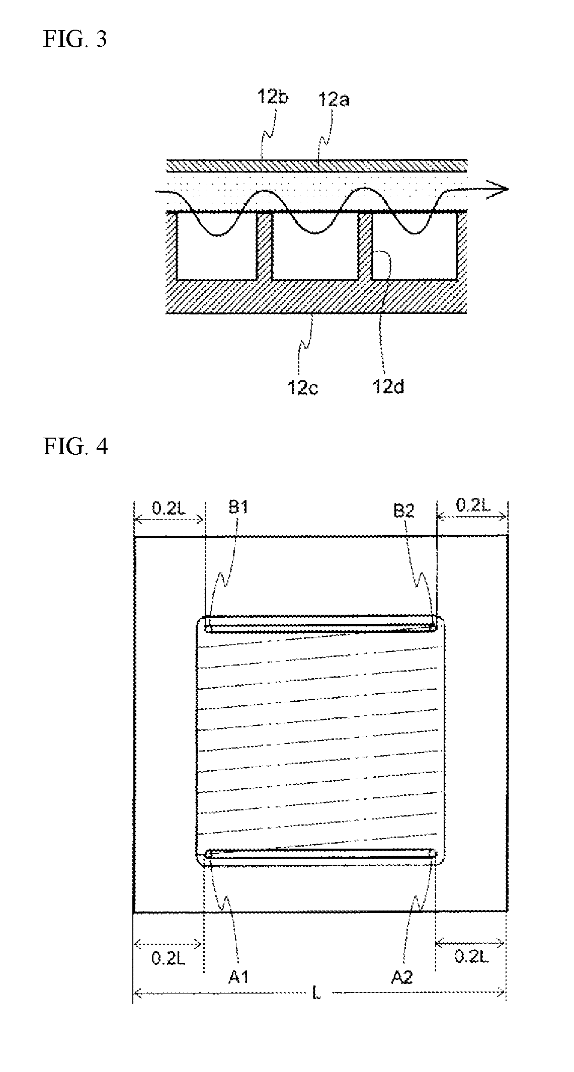
The present invention prevents the accumulation of by-product hydrogen gas inside the electrolytic cell and ensures uniform supply of the substance to be hydrogenated to the cathode for reliable reaction. This is achieved by providing partitions with appropriate spacing horizontal to the flow channel on the porous cathode of the organic hydride production apparatus, which improves the penetration of the raw material inside the cathode and reduces liquid substitution. Furthermore, the provision of partitions prevents current concentration and facilitates the reduction reaction of organic compounds with unsaturated bonds at high current efficiency and low electric power consumption rate.

Problems solved by technology

Although Japan is blessed with water resources, it cannot be claimed to be an ideal location for solar power or wind power, and is therefore currently forced to rely on the transport and storage of energy sources from overseas.
Further, although consideration is being given to the use of wind power generation and large-scale solar power generation to alleviate short-period output fluctuations, applying these sources to the alleviation of medium-term output fluctuations or large-scale energy transport is problematic.
However, because hydrogen is a gas at normal temperature and normal pressure, it suffers from the drawback of requiring special tankers for transport and storage.
However, a large-scale electrolytic cell for producing an organic hydride, which uses a liquid organic compound such as toluene as a raw material, and electrolyzes this raw material to obtain another liquid organic compound has yet to be implemented in a practical application, and structures for electrodes and conductive cathode supports that enable the raw material to be supplied smoothly to the electrode surface and the product to be removed from the surface are not yet known.
The technology disclosed in Non-Patent Document 1 relating to common brine electrolysis can be easily applied to the production of organic hydrides, but because fundamentally no gas is generated in the organic hydride production process, the electrodes and support structures used for common brine electrolysis cannot be used without modification.
Furthermore, other problems also arise in relation to applying the technology to organic hydride electrolytic cells due to the requirement for larger cells.
However, although porous materials having a large contact area have enabled the current value for electrodes to be increased, the current density for redox cells is limited to not more than 0.05 A / cm2, which does not satisfy the conditions required for the electrolytic cell of an organic hydride production apparatus.

Method used


Image

  • Apparatus for producing organic hydride and method for producing organic hydride using same
  • Apparatus for producing organic hydride and method for producing organic hydride using same
  • Apparatus for producing organic hydride and method for producing organic hydride using same

Examples


example 1

[0074]The hydrogenation reaction of toluene was evaluated electrochemically by supplying toluene to the cathode side and humidified hydrogen to the anode side of an electrode / membrane assembly produced by bonding noble metal-supporting carbon catalyst layers to both layers of a perfluorocarbonsulfonic acid-based membrane. Because the polarization of the hydrogen oxidation reaction at the anode is extremely small, the anode was deemed to also function as a pseudo reversible hydrogen electrode (RHE) counter electrode, and a carbon paper (35BC, manufactured by SGL Carbon AG) coated with 0.5 mgcm−2 of a Pt / C catalyst (TEC10E50E, manufactured by Tanaka Kikinzoku Kogyo K.K.) together with a Nafion solution (DE521, manufactured by DuPont Corporation) was used as the anode, and the carbon paper 35BC coated with 0.5 mgcm−2 of a PtRu / C catalyst (TEC61E54E, manufactured by Tanaka Kikinzoku Kogyo K.K.) together with the Nafion solution was used as the cathode. The electrode surface area was 25 ...

example 2

[0077]A cathode support having the type of planar structure illustrated in FIG. 9 was used. The structure of the cathode support 12c included one channel 21 and one 1.5 mm partition 12d of 1.5 mm for the channel 21 at both the top end and the bottom end of the support. With this exception, a similar test to Example 1 was performed. In the serpentine flow channel, hydrogen gas generation did not occur until 60 mAcm−2. The pressure differences at the cathode inlet and outlet were 0.004 MPa for ΔPL and 0.104 MPa for ΔPH. FIG. 10 illustrates a schematic partial cross-sectional view of the cathode chamber of the organic hydride production apparatus used in Example 2.

example 3

[0080]A cathode support 12c having the type of planar structure illustrated in FIG. 7 was used, in which parallel partitions 12d of width 1 mm were provided perpendicular to the flow direction at a pitch of 1 mm in the upper portion of the cathode support equivalent to 14% of the effective projected electrode area of the support. When toluene was supplied from the inlet in the lower portion of the cathode chamber, and electrolysis was conducted so that the toluene concentration at the outlet in the upper portion of the cathode chamber was controlled at 5%, hydrogen gas generation did not occur until 60 mAcm−2. The structure of the electrolytic cell had the type of structure illustrated in FIG. 1.


PUM


Abstract

An organic hydride production apparatus that enables the reduction reaction at the cathode of an organic compound having an unsaturated bond to proceed at high current efficiency and at a low electric power consumption rate, and a method for producing an organic hydride that uses this production apparatus. The production apparatus includes a solid polymer electrolyte membrane having proton conductivity, a cathode which is provided on one surface of the solid polymer electrolyte membrane and generates a hydride by reducing a substance to be hydrogenated, a cathode chamber which houses the cathode and is supplied with the substance to be hydrogenated, an electrode catalyst-containing anode which is provided on the other surface of the solid polymer electrolyte membrane and generates protons by oxidizing water, and an anode chamber which houses the anode and is supplied with an electrolytic solution, wherein the substance to be hydrogenated is supplied from the lower end of the cathode chamber, the production apparatus has a hydride outlet through which the product and the like is discharged from the upper end of the cathode chamber, and at least one partition with a width of not less than 0.1 mm is formed inside the cathode camber.

Description

TECHNICAL FIELD[0001]The present invention relates to an organic hydride production apparatus and a method for producing an organic hydride using the production apparatus (hereafter also referred to as simply an “electrolytic cell” and a “production method”), and relates more specifically to an organic hydride production apparatus that enables the reduction reaction at the cathode of an organic compound having an unsaturated bond to proceed at high current efficiency and at a low electric power consumption rate, and a method for producing an organic hydride that uses this production apparatus.BACKGROUND ART[0002]Electrical power consumption in Japan is about 1,000 TWh per year, and because thermal power generation is currently also being used to replace the power previously generated by nuclear power generation, the proportion of power generated by thermal power generation has reached 90%. On the other hand, although it is desirable that renewable energy sources such as solar power,...

Claims


Application Information

Patent Timeline
IPC IPC(8): C25B3/04C25B13/08C25B9/10C25B3/25C25B9/23
CPCC25B3/04C25B13/08C25B9/10C25B11/03C25B1/04C25B9/73C25B9/23C25B3/25Y02P20/133Y02E60/36C25B13/02
Inventor MITSUSHIMA, SHIGENORITAKAKUWA, YASUTOMONISHIKI, YOSHINORIKATO, AKIHIROMANABE, AKIYOSHI
Owner DE NORA PERMELEC LTD
Learn More