
Intelligent cooperative control system and method for multi-unit permanent magnet synchronous motor

Inactive Publication Date: 2017-11-09
NORTHEASTERN UNIV
View PDF7 Cites 2 Cited by
  • Summary
  • Abstract
  • Description
  • Claims
  • Application Information

AI Technical Summary

Benefits of technology

The intelligent cooperative control system for the multi-unit permanent magnet synchronous motor has the technical effects of achieving low-voltage high power, low-speed large-torque, and system redundancy control. The use of a double-parallel PWM rectifier circuit structure helps reduce reactive power loss and harmonic loss in an unbalanced power supply network environment. A resonant pole-type three-phase soft-switching inverter circuit improves the utilization of DC bus voltage and reduces device switching losses at high frequencies. A current control and speed estimation unit accurately estimates the rotor speed and phase angle information with low cost and high reliability. The controlled object is the multi-unit permanent magnet synchronous motor, solving issues of motor installation, transportation, and maintenance of high-power electric drive systems.

Problems solved by technology

At present, conventional high-power electric drive systems have many problems, mainly including that: in the aspect of system structures, most high-power electric drive systems use a single branch structure, causing high voltage level, no system redundancy and low reliability.
In the aspect of rectification, most system rectifier parts use an uncontrollable rectifier mode, causing low power factor and large reactive power drive loss which easily produce low frequency harmonics in an unbalanced power supply network environment, and therefore, it is difficult to achieve optimized control of reactive power.
In the aspect of inversion, most system inversion parts use a hard switching mode, causing large switching loss, especially during switching frequency increase and power increase of power devices.
In the aspect of motor control, mechanical sensors are most usually used to detect the positions of motor rotors, causing high system cost, low reliability and large maintenance workload.
In the aspect of motor manufacturing, most stators of traditional permanent magnet motors are manufactured by a whole processing method, causing problems of difficulty in high-voltage motor manufacturing, transportation, installation and maintenance, high transducer cost, low reliability, and the like.

Method used


Image

  • Intelligent cooperative control system and method for multi-unit permanent magnet synchronous motor
  • Intelligent cooperative control system and method for multi-unit permanent magnet synchronous motor
  • Intelligent cooperative control system and method for multi-unit permanent magnet synchronous motor

Examples


Embodiment Construction

[0043]An embodiment of the present invention is further described in connection with the accompanying drawings.

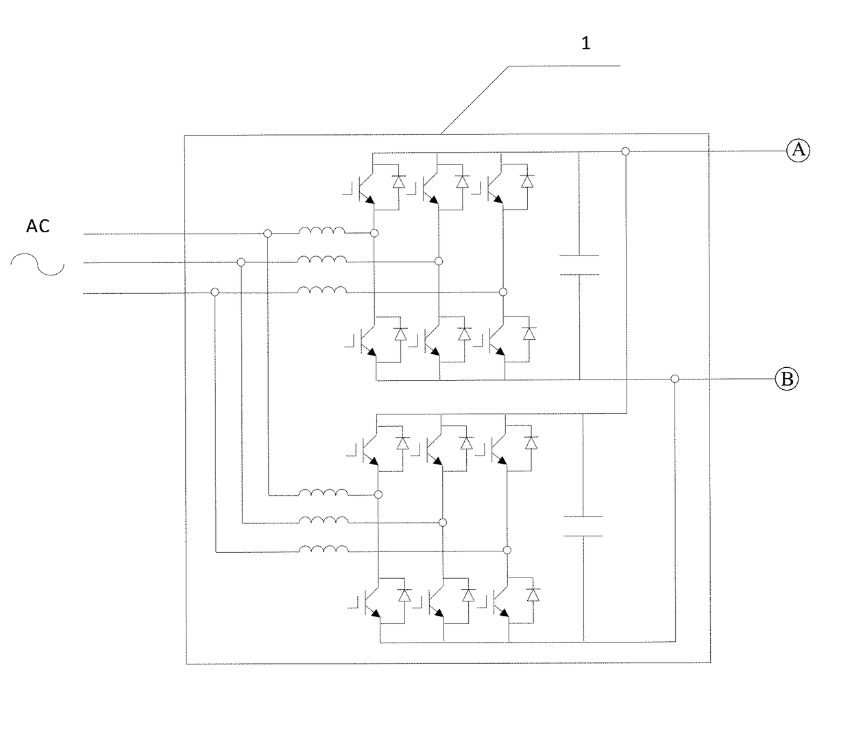
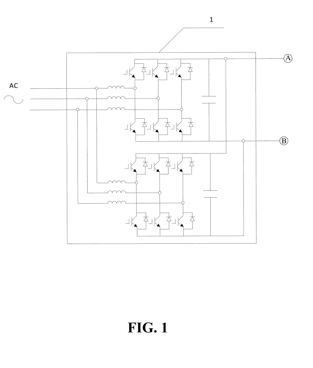
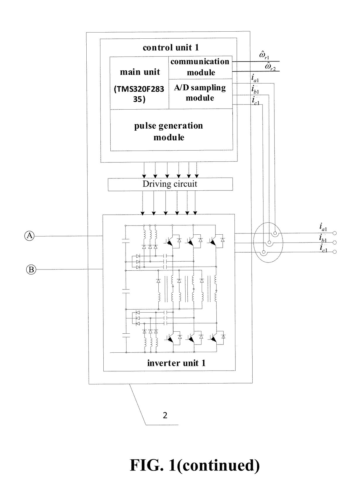
[0044]The intelligent cooperative control system for the multi-unit permanent magnet synchronous motor according to this embodiment of the present invention, as shown in FIG. 1, includes a double-parallel PWM rectifier circuit 1, a first permanent magnet motor cooperative control unit 2, a second permanent magnet motor cooperative control unit 3, a third permanent magnet motor cooperative control unit 4 and a multi-unit permanent magnet synchronous motor 5, wherein the first permanent magnet motor cooperative control unit 2, the second permanent magnet motor cooperative control unit 3 and the third permanent magnet motor cooperative control unit 4 cooperatively control three stator units of the multi-unit permanent magnet synchronous motor 5 through a parallel connection manner;

[0045]In this embodiment of the present invention, the double-parallel PWM rectifier circuit 1 is...


PUM


Abstract

An intelligent cooperative control system and method thereof. A parallel structure for low-voltage multi-module permanent magnet synchronous motor cooperative control units is adopted to realize control of low-voltage high power, control of low-speed large torque and system redundancy control; a double-parallel PWM rectifier circuit structure is used, when the system is in unbalanced power supply network environments; a resonant pole-type three-phase soft-switching inverter circuit is used as an inverter unit to improve utilization of DC bus voltage and to greatly reduce device switch losses at high frequencies; a current control and speed estimation unit is used, so that rotor speed and phase angle information is accurately estimated with low cost and high reliability; a controlled object is the multi-module permanent magnet synchronous motor, so that the problems of difficulties in motor installation, transportation and maintenance of a high-power electric drive system and the like are solved.

Description

BACKGROUND OF THE INVENTION1. Field of the Invention[0001]The present invention belongs to the technical field of power electronics and power drive, and particularly relates to an intelligent cooperative control system and method for a multi-unit permanent magnet synchronous motor.2. The Prior Arts[0002]High-power electric drive system occupies an important position in industrial production, and is widely applied in aspects of hoisting for large-scale mines, main propulsion for large ships, megawatt-class wind power generation, and the like. At present, conventional high-power electric drive systems have many problems, mainly including that: in the aspect of system structures, most high-power electric drive systems use a single branch structure, causing high voltage level, no system redundancy and low reliability. In the aspect of rectification, most system rectifier parts use an uncontrollable rectifier mode, causing low power factor and large reactive power drive loss which easily...

Claims


Application Information

Patent Timeline
IPC IPC(8): H02P21/24H02P6/28H02P6/15
CPCH02P21/24H02P6/15H02P6/28H02P25/22H02M5/4585H02M7/08H02M7/219H02K1/00H02K3/28H02K11/33Y02B70/10H02M7/4815H02M7/53876
Inventor ZHANG, HUAGUANGYAN, SHIJIEZHANG, BINGYIYAN, WEIHANGWANG, XULIU, XIUCHONGCHU, ENHUIXU, XIAOMIN
Owner NORTHEASTERN UNIV
Features
  • Generate Ideas
  • Intellectual Property
  • Life Sciences
  • Materials
  • Tech Scout
  • Unparalleled Data Quality
  • Higher Quality Content
  • 60% Fewer Hallucinations
Learn More