
Wireless soil profile monitoring apparatus and methods

Active Publication Date: 2017-11-16
PAULSEN KEITH LYNN
View PDF8 Cites 3 Cited by
  • Summary
  • Abstract
  • Description
  • Claims
  • Application Information

AI Technical Summary

Benefits of technology

The patent describes a new type of sensor that can measure the electrical properties of different media without causing oxidation or electroplating issues. This allows for a full range of measurements, from completely dry to fully saturated media. The sensor does this by measuring the permittivity and electrical conductivity of the media using both long and short window measurements. This makes the sensor more versatile and allows for accurate measurements in completely dry or wet conditions. Overall, this new sensor has a longer lifespan and is more reliable for various applications.

Problems solved by technology

Measuring soil moisture content at a municipal or industrial scale is complex and includes a number of well-known problems in order to measure to an adequate level of accuracy and reproducibility at a reasonable cost.
Often at the municipal and industrial level, deployment of a large number of sensors impacts the overall system cost because of the requirement to frequently replace batteries and the need to dean sensor probes to ensure adequate accuracy.
There are a number of known techniques for measuring soil water content including (a) Neutron probe—uses radioactive material which is expensive and is typically inaccurate in topsoil (b) Matric potential—uses low cost gypsum which has slow response and lacks durability (c) Tensiometers—require regular maintenance (d) Time Domain Reflectometer—is expensive and is only accurate up to 65% VWC (e) Capacitive—is low cost but is susceptible to electrical conductivity issues (f) Frequency—low cost but is susceptible to electrical conductivity issues and is limited in range (g) Impedance Matching—expensive and limited range.
This is in part due to soil non-homogeneity and variation of soil composition.
The result of these issues it that most reasonably priced solutions do not function or measure VWC above 65% water saturation.
The dielectric coating is only partially effective at reducing sensitivity to soil conductivity which results in a moisture content sensor with sensitivity to soil conductivity and salinity.
Coatings are also subject to wear and do not address the issue of charge stealing by the earth.
Because these techniques depend on current flow into the earth, it is naturally susceptible to conductance of soil to ambient ground.
However, this technique also suffers near total loss of signal at high saturation.
Often the previously known sensors require battery replacement each season which is a significant limitation to large scale deployment.
Cost of the sensors and vulnerability of current sensors to tampering further prohibits wide deployment in unsecured areas.
As a result, all of the current techniques have proven uses in particular segments but they suffer at least in terms of cost, complexity or accuracy, thus preventing ubiquitous adoption for large scale data collection such as in a metropolitan or industrial sensor network.

Method used


Image

  • Wireless soil profile monitoring apparatus and methods
  • Wireless soil profile monitoring apparatus and methods
  • Wireless soil profile monitoring apparatus and methods

Examples


first embodiment

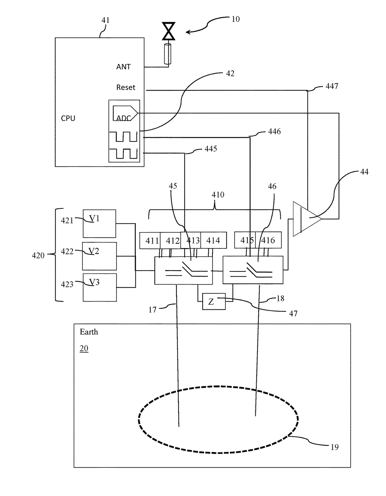
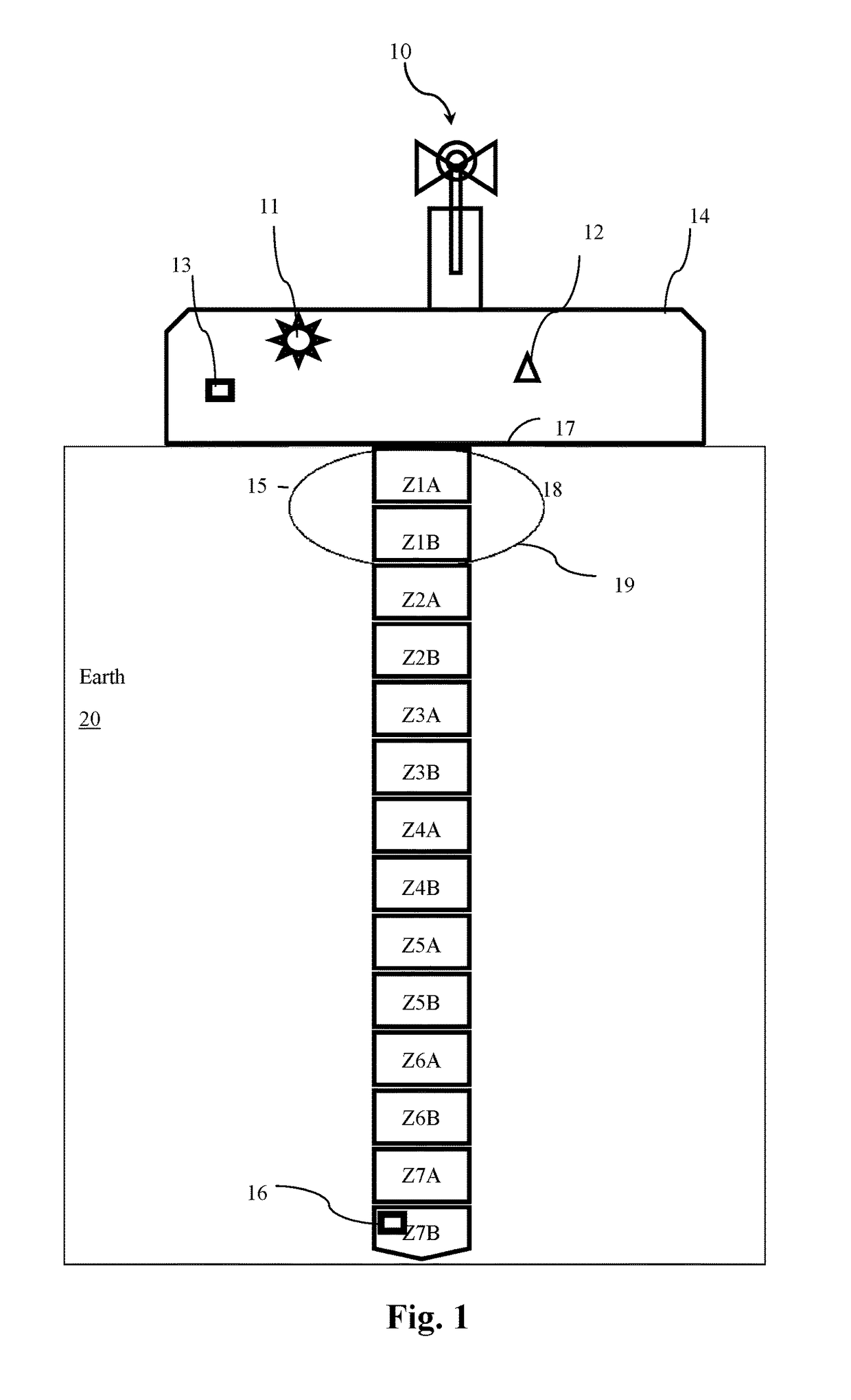
[0056]FIG. 1 shows a volumetric water content sensor comprising an integrator circuit for measuring soil moisture content 1. The VWC sensor measures moisture content at seven zones within the soil with each zone having a distinct volume of influence 19. A volume of influence is the space within the soil in electrical proximity of probe 17 and probe 18. The apparatus shown in FIG. 1 also includes a radio and radio antenna 10. The radio provides direct connection and logging of sensor data to a big data server via network including the Internet, WiFi, WiFi Max, LoRaWan™. The apparatus further includes a plurality of sensors for measuring other parameters which may be used in combination with the water content measurement for predicting soil conditions. The plurality of sensors may include: a topsoil temperature sensor 15, a root temperature sensor 16 and an air temperature sensor 13, a humidity sensor 12 and a light sensor 11. The electronics for the moisture sensor are housed in an e...

second embodiment

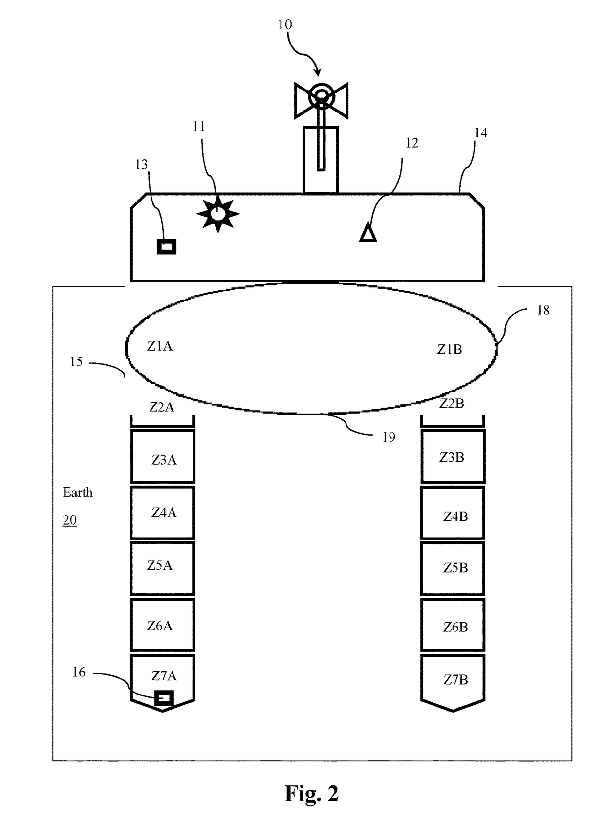
[0059]The second embodiment shown in FIG. 2 includes the means for measuring soil moisture content also at several levels within the soil and includes the plurality of sensors. The probes in this embodiment, however, are spaced horizontally and provide for a larger volume of influence by further separating the probes. Volumes of greater than a cubic meter can be sampled using the method of this invention. It is noted that previously available sensors measure up to only a few centimeters.

third embodiment

[0060]FIG. 3 illustrates a third embodiment which includes a means for measuring topsoil moisture content at numerous locations. The probe conductors in this embodiment are spaced around a wheel such as on the wheel of a tractor or lawn mower. Samples may be correlated with GPS coordinates to create a detailed topsoil moisture map.

[0061]Unlike traditional methods of moving a sensor above the surface or dragging a sensor across the material to be sampled, the current invention provides a consistent amount of pressure and contact with the soil.

[0062]The current apparatus is useful to reduce the issues associate with air gaps between the soil and sensor probes. The current invention also applies to radio frequency backscatter measurement of volumetric water content as well as time domain reflectometry measurement of volumetric water content.


PUM


Abstract

An in situ ultra-low power contactless measurement apparatus and method suitable for micro-electronics in big data applications for continuously reporting a soil moisture profile at various zones.

Description

FIELD OF THE INVENTION[0001]The invention relates generally to measurement devices and more specifically to measurement devices for measuring characteristics of a soil profile including volumetric water content, electrical conductivity and temperature at various depths in the soil.BACKGROUND OF THE INVENTION[0002]The present invention is primarily focused on taking accurate measurements of volumetric water content (VWC) in a variety of media, including but not limited to: soil, wood, concrete, building materials, clothing, and the like. This invention is useful in such applications as crop irrigation, lawn care, gardening and other landscaping applications, laundry systems, non-destructive testing for ground water infiltration into buildings, and a full range of moisture environments ranging from dry to completely saturated.[0003]The present invention is particularly suited for big data environments such as large scale deployment of numerous sensors such as industrial irrigation sys...

Claims


Application Information

Patent Timeline
IPC IPC(8): G01N27/22H04Q9/00
CPCG01N27/223G01N27/228H04Q9/00H04Q2209/40
Inventor PAULSEN, KEITH LYNN
Owner PAULSEN KEITH LYNN
Learn More