On-board aircraft electrochemical system

Active Publication Date: 2017-11-16
HAMILTON SUNDSTRAND CORP
View PDF2 Cites 35 Cited by
  • Summary
  • Abstract
  • Description
  • Claims
  • Application Information

AI Technical Summary

Problems solved by technology

Bleed air from an aircraft engine or from an onboard auxiliary power unit can provide a source of compressed air; however, this can reduce available engine power and also must compete with other onboard demands for compressed air, such as the onboard air environmental conditioning system.
Moreover, certain flight conditions such as during aircraft descent can lead to an increased demand for NEA at precisely the time when engines could be throttled back for fuel savings so that that maintaining sufficient compressed air pressure for meeting the pneumatic demands may come at a s

Method used


Image

  • On-board aircraft electrochemical system
  • On-board aircraft electrochemical system
  • On-board aircraft electrochemical system

Examples


Embodiment Construction

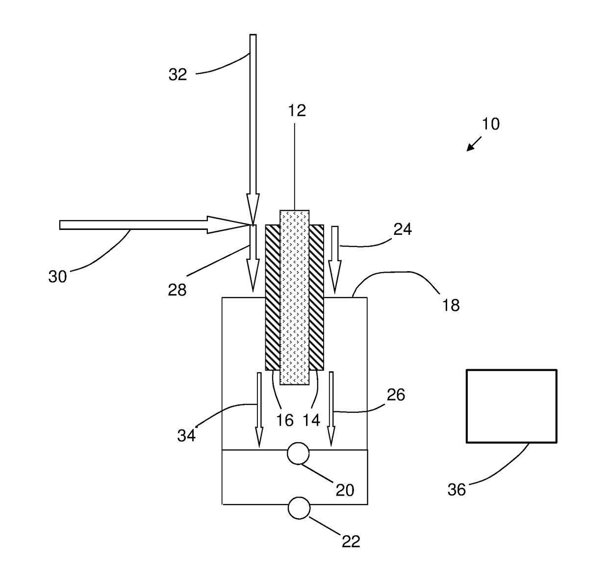
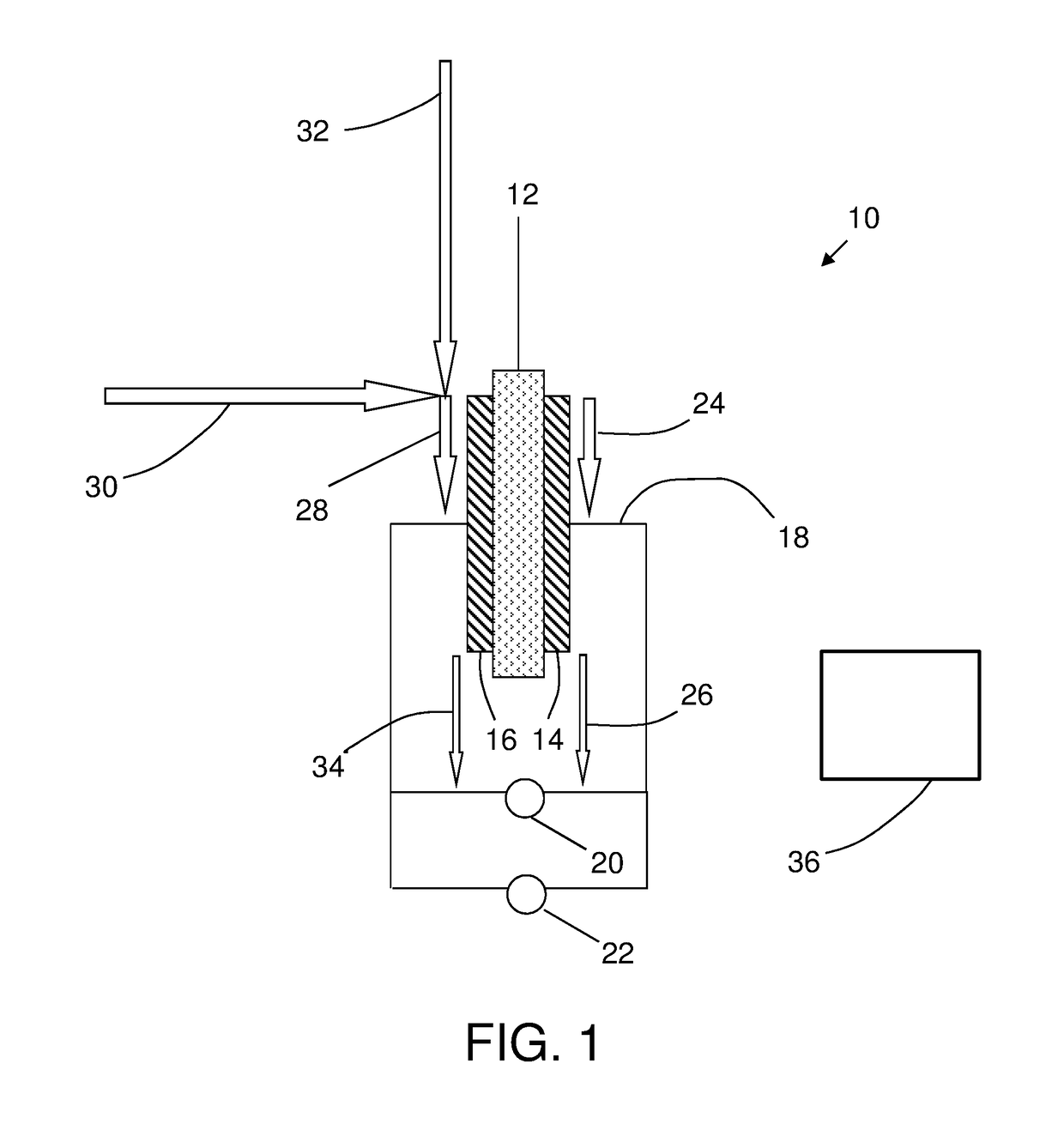
[0014]Referring now to the Figures, in which the same numbering may be used in more than one Figure to represent the same feature without the necessity of explicit repetition of the description for each Figure, FIG. 1 schematically depicts an electrochemical cell 10. The electrochemical cell 10 comprises an electrolyte 12 having a cathode 14 disposed on one side and an anode 16 disposed on the other side. Cathode 14 and anode 16 are positioned adjacent to, and preferably in contact with the electrolyte 12 and can be solid metal layers deposited (e.g., by vapor deposition) onto the electrolyte 12, or can have structures comprising discrete catalytic particles adsorbed onto a porous substrate that is attached to the electrolyte 12. Alternatively, the catalyst particles can be deposited on high surface area powder materials (e.g., graphite or porous carbons or metal-oxide particles) and then these supported catalysts may be deposited directly onto the electrolyte 12 or onto a porous su...


PUM


Abstract

An onboard electrochemical system of an electrochemical cell including a cathode and an anode separated by an electrolyte separator is selectively operated in either of two modes. In a first mode of operation, water or air is directed to the anode, electric power is provided to the anode and cathode to provide a voltage difference between the anode and the cathode, and nitrogen-enriched air is directed from the cathode to an aircraft fuel tank or aircraft fire suppression system. In a second mode of operation, fuel is directed to the anode, electric power is directed from the anode and cathode to one or more aircraft electric power-consuming systems or components, and nitrogen-enriched air is directed from the cathode to a fuel tank or fire suppression system.

Description

BACKGROUND[0001]This disclosure relates to aircraft systems, and in particular to an on-board aircraft electrochemical system.[0002]It is recognized that fuel vapors within fuel tanks become combustible in the presence of oxygen. An inerting system decreases the probability of combustion of flammable materials stored in a fuel tank by maintaining a chemically non-reactive or inert gas, such as nitrogen-enriched air, in the fuel tank vapor space also known as ullage. Three elements are required to initiate and sustain combustion: an ignition source (e.g., heat), fuel, and oxygen. Combustion may be prevented by reducing any one of these three elements. If the presence of an ignition source cannot be prevented within a fuel tank, then the tank may be made inert by: 1) reducing the oxygen concentration, 2) reducing the fuel concentration of the ullage to below the lower explosive limit (LEL), or 3) increasing the fuel concentration to above the upper explosive limit (UEL). Many systems ...

Claims


Application Information

Patent Timeline
IPC IPC(8): H01M8/04746H01M8/04082H01M8/1231H01M8/04858
CPCH01M8/04753H01M8/04201H01M8/04761H01M8/04865H01M8/1231H01M2250/20A62C3/08A62C99/0018B64D37/32B64D2041/005Y02E60/50Y02T50/40Y02T90/40Y02E60/36C25B1/04B64D2045/009
Inventor RHEAUME, JONATHAN
Owner HAMILTON SUNDSTRAND CORP
Why Eureka
Try Eureka