Supercritical Water Separation Process

a separation process and supercritical water technology, applied in the direction of separation processes, supercritical condition processes, hydrocarbon oil treatment products, etc., can solve the problems of high cost of construction and operation, large amount of solvent in the deafphalting process, and 80% of the vacuum distillation system of refineries, so as to achieve rapid reduction of scw density, good separation performance, and fast separation rate

Active Publication Date: 2018-01-11
APPLIED RES ASSOCS INC
View PDF1 Cites 5 Cited by
  • Summary
  • Abstract
  • Description
  • Claims
  • Application Information

AI Technical Summary

Benefits of technology

[0009]The present invention is a continuous process and system for the removal of metals, minerals, asphaltenes, and resins from a contaminated feedstock. Contaminated feedstock (which may or may not be referred to herein as organic) is defined here as any petroleum crude oil, crude oil fraction, refinery intermediate stream, contaminated hydrocarbon, or contaminated renewable oil including algal oils, pyrolysis oils, or waste oils and greases. The present invention takes advantage of the physical and chemical properties of supercritical water (SCW), defined as water above 374° C. and 22.1 MPa to effect the desired separation of contaminants from organic materials. At a temperature and pressure above the critical point of water (374° C., 22.1 MPa), the desirable nonpolar organic compounds become miscible in SCW and the undesirable polar compounds, asphaltenes, and resins become immiscible. Under proper conditions, immiscible components and solids will settle via gravity out of the SCW and oil solution. An important property of supercritical water is the rapid decrease in the density of SCW with temperature near the critical point of water. This relationship is shown in Table 1 for the temperature range of interest.
[0010]The temperature-density relationship is an important feature of the present invention for several reasons that include, but are not limited to the following: 1) as SCW density decreases, the ratio of the density of the immiscible constituents to the density of SCW increases which, in turn, increases the settling rate of the immiscible constituents and thus allows for a faster separation rate between the desirable organic compounds and undesirable polar compounds, asphaltenes, and resins, 2) creation of a vertical density gradient, wherein the highest density is in the bottom, concentration zone and the lowest density is in the upper zone of the separation vessel, creates an inherently stable system which prevents convective mixing caused by a density inversion (higher density on the top than on the bottom), 3) the vertical density gradient permits continuous up-flow operation wherein SCW-soluble constituents are continuously removed with the SCW from the upper zone of the separation vessel and immiscible constituents are continuously removed from the bottom zone of the separation vessel, and 4) the inherently stable nature of the separation vessel, established by the vertical density gradient that prevents convective mixing, enables scale up to larger-diameter, higher-volume, commercial-scale systems.
[0011]Another feature of the present invention is that the separation vessel provides an operating environment in which the miscible hydrocarbon components are not reactive. Good separation performance is achieved at opera...

Problems solved by technology

However, only about 80% of refineries have vacuum distillation systems because they are expensive to build and operate.
The solvent deasphalting process...

Method used


Image

  • Supercritical Water Separation Process
  • Supercritical Water Separation Process
  • Supercritical Water Separation Process

Examples


example 1

ic Tower Bottoms (ATB) Separation

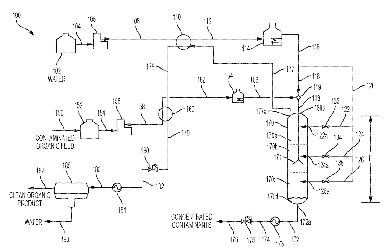
[0044]A bench-scale separation system was configured as shown in FIG. 1. In this configuration, SCW 118 and contaminated oil 166 were mixed at tee connection 119 immediately before being fed into the separation vessel 170. A control stream of SCW 126 was also fed at location 126a into separation vessel 170 just below the mixing zone. The inside diameter of the bench-scale separation vessel was 2.8 cm (1.1 inches) and the height of the vessel was 1.65 meters (65 inches). The contaminated organic feed oil was an atmospheric tower bottoms (ATB) from a refinery in the intermountain west. This particular ATB had been previously treated in a ROSE solvent deasphalting system so it exhibited relatively low asphaltene content. However, this ATB did contain metals, sulfur, and had a relatively high Conradson Carbon Residue (CCR).

[0045]The bench-scale separation system was operated with continuous flow of ATB, mix water, control water. Overhead product water an...

example 2

Bitumen Separation

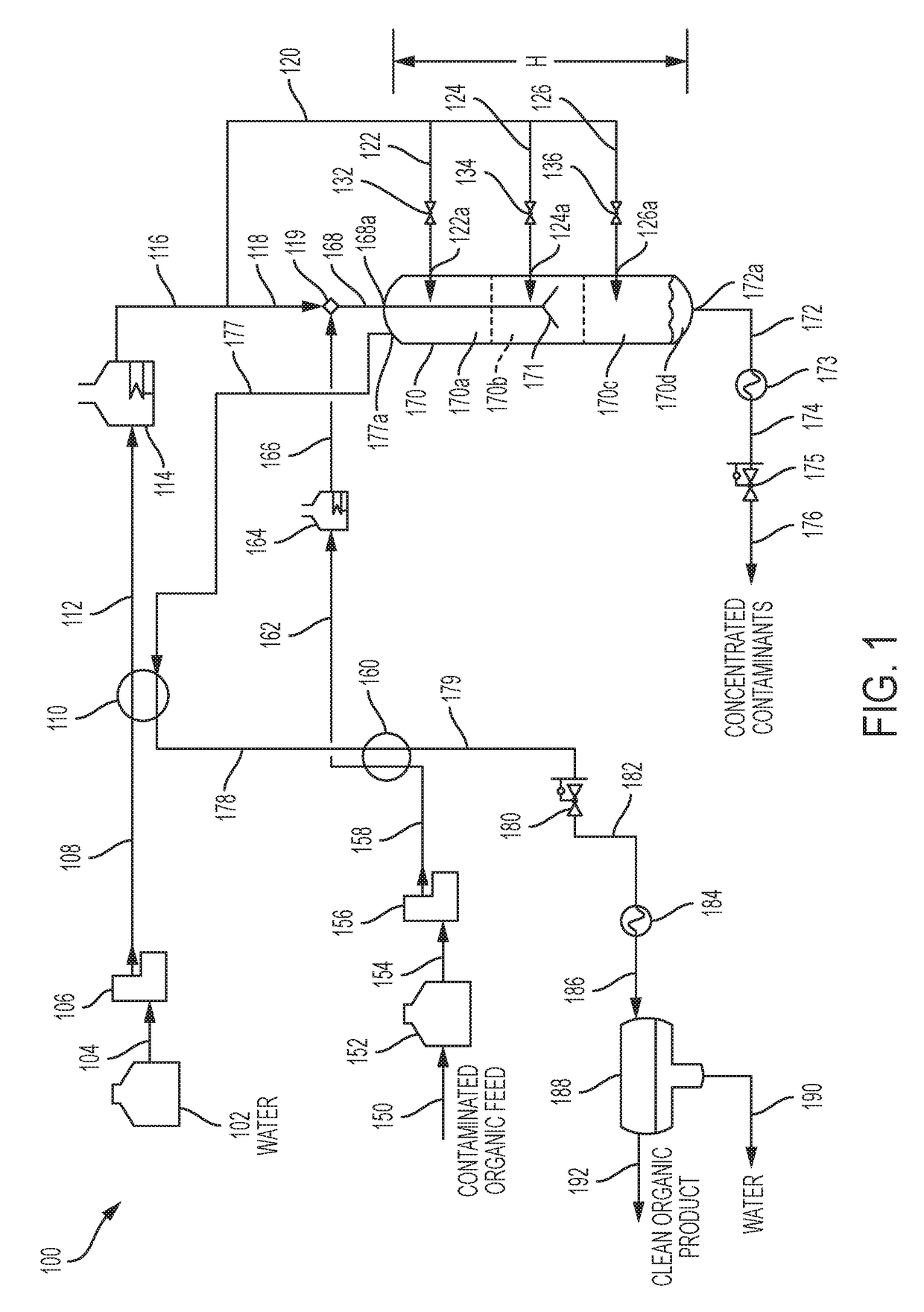
[0047]A bench-scale separation system was configured as shown in FIG. 1. In this configuration, SCW 118 contaminated organic feed oil 166 and control SCW 126 were delivered to the separation vessel in the same manner as Example 1. The contaminated organic feed oil was Canadian bitumen that was produced by the SAGD process (Steam-Assisted, Gravity Drain). In the SAGD process, steam is pumped into the bitumen-containing geologic formation and a hot slurry of water and bitumen is recovered. Water had been previously removed from this sample of bitumen. However, the supercritical water separation system is capable of processing the bitumen and water slurry without the need to separate the water. The density and viscosity of most Canadian bitumens are too high to permit transporting by pipeline without extensive upgrading. The purpose of this example was to demonstrate that the present invention can reduce the density and viscosity of the bitumen to meet pipeline requir...


PUM


Abstract

A supercritical water separation process and system is disclosed for the removal of metals, minerals, particulate, asphaltenes, and resins from a contaminated organic material. The present invention takes advantage of the physical and chemical properties of supercritical water to effect the desired separation of contaminants from organic materials and permit scale-up. At a temperature and pressure above the critical point of water (374° C., 22.1 MPa), nonpolar organic compounds become miscible in supercritical water (SCW) and polar compounds and asphaltenes become immiscible. The process and system disclosed continuously separates immiscible contaminants and solids from the supercritical water and clean oil product solution. The present invention creates a density gradient that enables over 95% recovery of clean oil and over 99% reduction of contaminants such as asphaltenes and particulate matter depending on the properties of the contaminated organic material.

Description

CROSS REFERENCE TO RELATED APPLICATION[0001]This application claims the benefit of U.S. Provisional Application No. 62 / 359,896, filed Jul. 8, 2016, which is hereby incorporated in its entirety by reference.FIELD OF THE INVENTION[0002]The present invention is directed to a supercritical water (SCW) separation process and system for the rapid separation of inorganic and organic contaminants, such as salts, minerals, metals, asphaltenes, particulate matter, catalyst fines, and coke precursors from contaminated organic materials such as petroleum and renewable oils. The process and system is characterized by mixing of supercritical water and a contaminated organic stream, extraction of soluble organic constituents by SCW, and gravity separation of insoluble contaminants by establishing and maintaining a density gradient in the separation vessel.BACKGROUND OF THE INVENTION[0003]Petroleum refiners are continually seeking to improve refinery throughput and increase the yields of the highes...

Claims


Application Information

Patent Timeline
IPC IPC(8): C10G55/04C10G21/00B01D11/04C10G27/00C10G47/32B01J3/00C10G21/08
CPCC10G55/04C10G2400/04C10G21/08C10G21/003C10G27/00B01D11/0403B01J3/008C10G2300/1074C10G2300/202C10G2300/206C10G2300/304C10G2300/4006C10G2300/4012C10G2300/805C10G47/32C10G31/08B01D11/0488B01D11/0446C10G49/18C10L9/086
Inventor COPPOLA, EDWARD N.RED, JR., CHARLESNANA, SANJAYPELT, KENNETH D.WAHLGREN, JOCELYN MARIE
Owner APPLIED RES ASSOCS INC
Why Eureka
Try Eureka