High efficiency spin torque switching using a ferrimagnet

a high-efficiency, ferrimagnetic technology, applied in the direction of magneto-body, instrument, substrate/intermediate layer, etc., can solve the problems of insufficient thermal stability and external magnetic field resistance to make the resulting device viable, and the switching efficiency is still lower than desired, so as to improve external magnetic field resistance and switching efficiency, improve thermal stability, and reduce current switching

Active Publication Date: 2018-02-01
NAT UNIV OF SINGAPORE
View PDF8 Cites 5 Cited by
  • Summary
  • Abstract
  • Description
  • Claims
  • Application Information

AI Technical Summary

Benefits of technology

[0007]Improved thermal stability, external magnetic field resistance and switching efficiency may be achieved in spin torque device by using a thick (e.g., >1 nm, and preferably >=2-6 nm) ferrimagnet (FIM) layer, instead of a thin (e.g., <1-2 nm) FM layer in the device's stack. The FIM layer may be composed of a cobalt-gadolinium (Co—Gd) alloy, cobalt-terbium (Co—Tb) multilayers, or other materials that provide anti-ferromagnetic coupling between two sub-lattices. Bulk perpendicular magnetic anisotropy (PMA) of the FIM may aid in depositing a thick film, and such thickness may provide increased thermal stability. The FIM may also be resilient to external magnetization due to its intrinsic high anisotropy, because of the negative exchange interaction between the two sub-lattices. Further, the negative exchange interaction between the two sub-lattices of the FIM may allow for low current switching. For example, an SOT device utilizing a FIM layer may be an order of magnitude (e.g., 20 times) more efficient in a traditional FM-based SOT device. The use of a FIM layer may improve the STT devices (e.g., STT MRAM) that are soon to be commercially available, and may help render SOT device (e.g., SOT MRAM) more commercially viable.

Problems solved by technology

Therefore, sufficient thermal stability and external magnetic field resistance generally have not been achieved to make the resulting devices viable under practical (i.e. real world) operational conditions.
In addition, achieved switching efficiency has still been lower than desired (that is, the required switching current is still higher than desired).

Method used


Image

  • High efficiency spin torque switching using a ferrimagnet
  • High efficiency spin torque switching using a ferrimagnet
  • High efficiency spin torque switching using a ferrimagnet

Examples


Embodiment Construction

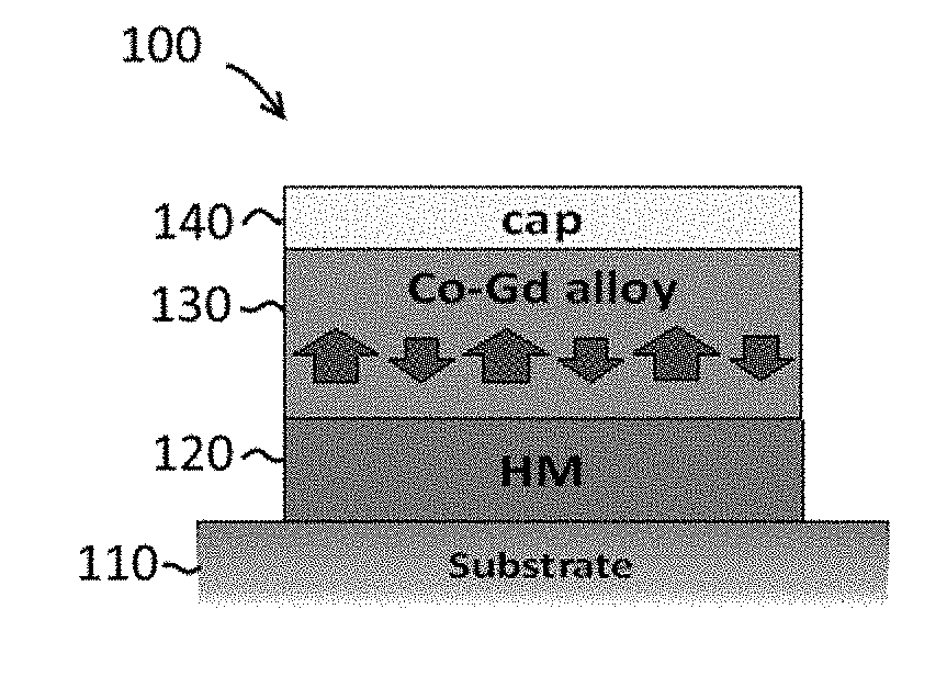
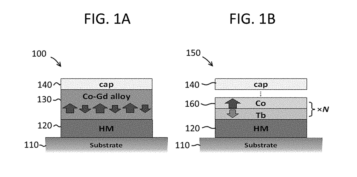
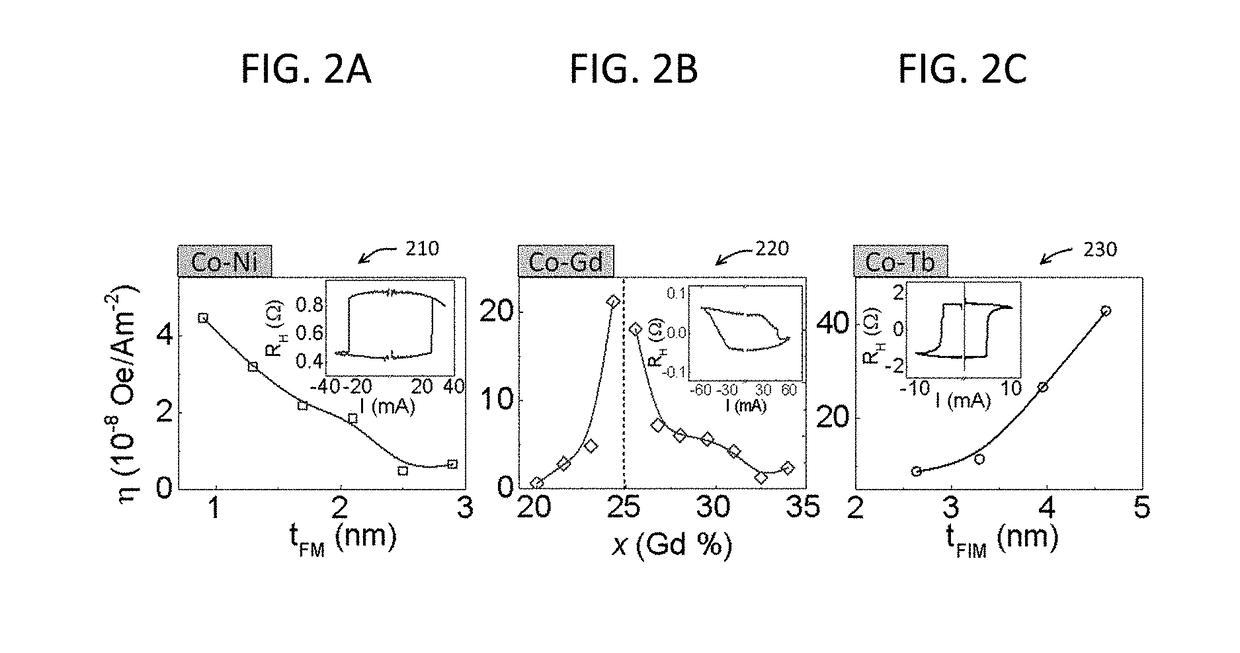
[0019]FIGS. 1A and 1B are diagrams of example spin torque devices that utilize a FIM layer 130, 160. In this and below examples, the spin torque devices take the form of SOT devices 100, 150, but it should be remembered that an FIM layer may alternatively be used in other types of spin torque devices, including STT devices. The first SOT device 100 includes a substrate 110 (e.g., thermally oxidized silicon), an HM layer 120 (e.g., 10 nm of Pt) that serves as a spin current source, a single FIM layer 130 (e.g., 6 nm thick Co—Gd alloy, for example, grown using a radio frequency (rf) and direct current (DC) magnetron sputtering system), and a capping layer 140 (e.g., of silicon oxide (SiO2)). The Co and Gd concentration in the layers may be in the range of Co83Gd17 to Co64Gd36. The second SOT device 150 includes a substrate 110, an HM layer 120 (e.g., 4 nm of Pt) that is serves as a spin current source, a multilayer FIM layer 160 (e.g., 0.34 nm of Tb and0.32 nm of Co as a bilayer pair,...


PUM

PropertyMeasurementUnit
thicknessaaaaaaaaaa
thicknessaaaaaaaaaa
thicknessaaaaaaaaaa

Abstract

In one embodiment, a spin torque device uses a thick (e.g., >1 nm, and preferably >=2-6 nm) ferrimagnet (FIM) layer, instead of a thin (e.g., <1-2 nm) FM layer in the device's stack. The FIM layer may be composed of a cobalt-gadolinium (Co—Gd) alloy, cobalt-terbium (Co—Tb) multilayers, or other materials that provide anti-ferromagnetic coupling between two sub-lattices. Negative exchange interaction between the two sub-lattices of the FIM may allow for low current switching. High thermal stability and external magnetic field resistance may also be achieved.

Description

RELATED APPLICATION[0001]The present application claims priority to Singapore Patent Application No. 10201606203Q, titled High Efficiency Spin Torque Switching Using a Ferrimagnet, filed Jul. 27, 2016 by Applicant National University of Singapore, the contents of which are incorporated by reference herein in their entirety.BACKGROUNDTechnical Field[0002]The present disclosure relates generally to spin torque devices (e.g., spin transfer torque (STT) or spin-orbit torque (SOT) devices), and more specifically, to techniques for improving thermal stability, external magnetic field resistance and switching efficiency in spin torque devices.Background Information[0003]Spin torque devices, such as spin torque magnetic random access memory (MRAMs), manipulate magnetization directions in a magnetic tunnel junction or spin valve to store information or for other purposes. Magnetization direction may be manipulated using current-induced STT. STT techniques have advanced over a number of years...

Claims


Application Information

Patent Timeline
Patent Type & Authority Applications(United States)
IPC IPC(8): H01L43/10H01F10/32G11C11/16H01L43/08
CPCH01L43/10H01L43/08G11C11/161G11C11/165H01F10/3222G11C11/18G11C11/1675H01F10/329H10N50/85H10N50/10
Inventor HYUNSOO, YANGMISHRA, RAHULJIAWEI, YU
Owner NAT UNIV OF SINGAPORE
Why Eureka
Try Eureka