
Laser surgery apparatus for contact laser surgery

a laser surgery and laser surgery technology, applied in the field of laser surgery apparatus for contact laser surgery, can solve the problems of mechanism cuts, difficult to treat large tissue areas in an even fashion, excessive tissue vaporization and carbonization, etc., and achieve the effect of reducing fluence, effective cutting, and reducing the shear force needed

Active Publication Date: 2018-03-01
MAX PLANCK GESELLSCHAFT ZUR FOERDERUNG DER WISSENSCHAFTEN EV
View PDF5 Cites 0 Cited by
  • Summary
  • Abstract
  • Description
  • Claims
  • Application Information

AI Technical Summary

Benefits of technology

The present invention provides a laser system for cutting tissue that reduces tissue damage by using a low laser fluence. The laser system uses pulsed IR laser radiation to heat the tissue with minimal adverse effects on the surrounding tissue. The heated tissue is then cut with a mechanical cutting edge, such as the uncoated contact surface of the fiber tip. This method of cutting reduces bleeding and allows for precise and safe tissue removal.

Problems solved by technology

However, as substantially all of the laser energy is delivered to the tissue at the point of contact (i.e. as substantially all of the laser energy is delivered to an extremely small tissue area), the use of contact delivery systems often results in excessive tissue vaporization and carbonization, thus making it quite difficult to treat large tissue areas in an even fashion.
This mechanism cuts by slow heating with significant damage to surrounding tissue.
According to reference [2], the new generations of pulsed medical lasers ablate tissue with a smaller damage zone in the adjacent tissue in the range of micrometers, but suffer from ionization of the tissue creating toxic free radicals or missing coagulation to stop bleeding.

Method used


Image

  • Laser surgery apparatus for contact laser surgery
  • Laser surgery apparatus for contact laser surgery
  • Laser surgery apparatus for contact laser surgery

Examples


Embodiment Construction

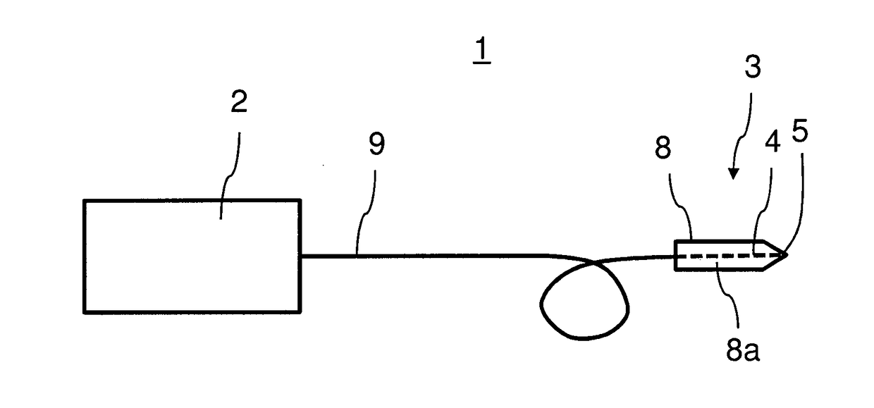
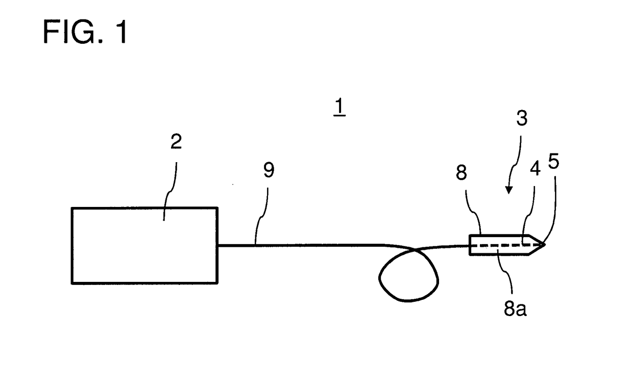
[0053]FIG. 1 shows a schematic illustration of an embodiment of a laser surgery apparatus 1 for contact laser surgery according to the invention.

[0054]The laser surgery apparatus 1 comprises a picosecond infrared laser (PIRL) source 2 that is configured to generate pulsed IR laser light of a wavelength falling within a range from 1 μm to 20 μm, of a pulse duration falling within a range from 100 fs to 10 ns, and of a repetition rate falling within a range from 1 Hz to 1 MHz.

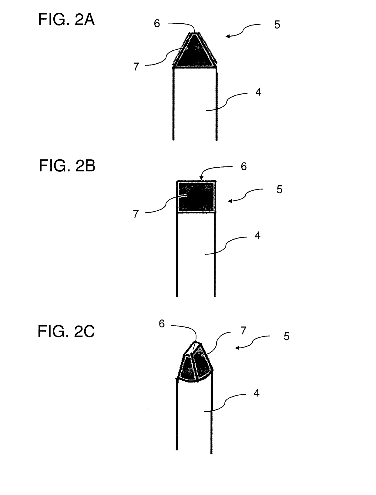
[0055]The laser surgery apparatus 1 further comprises a contact laser scalpel 3 for contact laser surgery that comprises an optical fiber 4 of IR laser radiation transmissive material which terminates at an optical fiber tip 5. The fiber tip 5 comprises an exposed core region that is tapered and has a form of a mechanical blade shape (cf. FIGS. 2A to 3F) and is disposed at a distal end of the scalpel 3 for contacting a tissue to be cut. Thus, the shaped fiber tip 5 extends forwardly of the handpiece 8 to define a...


PUM

PropertyMeasurementUnit
Temperatureaaaaaaaaaa

Abstract

The present invention relates to a laser surgery apparatus for contact laser surgery and to a method of using the laser surgery apparatus. The laser surgery apparatus (1) comprises a contact laser scalpel (3) for contact laser surgery, the contact laser scalpel (4) comprising an optical fiber (4) of IR laser radiation transmissive material and terminating at an optical fiber tip (5) having an exposed core region, and support means for holding said fiber and for positioning said scalpel (3). Said fiber tip (5) is tapered and disposed at a distal end of the scalpel (3) for contacting a tissue to be cut and comprises an uncoated contact surface (6) for transmit ting laser radiation and a guiding surface that is at least partially reflective to laser radiation and provided such that laser radiation guided by said optical fiber (4) to said fiber tip (5) will be at least partially reflected by said guiding surface and emitted through said uncoated contact surface. The contact laser surgery apparatus further comprises a pulsed laser source (2) adapted to provide pulse durations in the femtosecond, picosecond and / or nanosecond range, and light transmitting means (9) connecting said laser source (2) to said optical fiber (4) of said scalpel (3) for conveying laser radiation from said laser source (2) to said optical fiber (4) such that the conveyed laser light is emitted at said uncoated contact surface of the fiber tip.

Description

FIELD OF THE INVENTION[0001]The present invention relates to a laser surgery apparatus for contact laser surgery and to a method of using the laser surgery apparatus.BACKGROUND OF THE INVENTION[0002]In the present specification, reference is made to the following prior art illustrating the technical background.[0003][1] S. Amini-Nik, D. Kraemer, M. L. Cowan, K. Gunaratne, P. Nadesan, B. a Alman, and R. J. D. Miller, “Ultrafast mid-IR laser scalpel: Protein signals of the fundamental limits to minimally invasive surgery,” PLoS One, vol. 5, no. 9, pp. 1-6, January 2010.[0004][2] K. Franjic, M. L. Cowan, D. Kraemer, and R. J. D. Miller, “Laser selective cutting of biological tissues by impulsive heat deposition through ultrafast vibrational excitations,” Opt. Express, vol. 17, no. 25, pp. 22937-59, December 2009.[0005][3] J. a Sherman and H. T. Davies, “Ultracision: The harmonic scalpel and its possible uses in maxillofacial surgery,” Br. J. Oral Maxillofac. Surg., vol. 38, no. 5, pp. ...

Claims


Application Information

Patent Timeline
IPC IPC(8): A61F9/008A61F9/009
CPCA61F9/00821A61F9/00802A61F9/009A61B18/22A61F9/00836A61F2009/00861A61N5/0625A61B17/3211A61B18/203A61B2018/00107A61B2018/2233A61B2018/2272A61B2018/2288A61N2005/063A61N2005/0644A61B2018/225A61N5/067
Inventor MILLER, R.J. DWAYNEMAIER, STEPHANIEKRUBER, SEBASTIANHANSEN, NILS-OWE
Owner MAX PLANCK GESELLSCHAFT ZUR FOERDERUNG DER WISSENSCHAFTEN EV
Learn More