
Conditioning method of gas turbine engine components for aerodynamic noise reduction

Active Publication Date: 2018-05-03
ENVAEROSPACE
View PDF1 Cites 0 Cited by
  • Summary
  • Abstract
  • Description
  • Claims
  • Application Information

AI Technical Summary

Benefits of technology

The patent aims to reduce the aerodynamic noise of gas turbine engine components. The technical effect is to minimize the noise generated by the engine's components, making it quieter and more efficient.

Problems solved by technology

Higher compressor pressures and temperatures can allow for greater efficiencies unfortunately with a higher noise level.
Especially, but not limited to blades and vanes, surface roughness can be the result of deposition, erosion, or surface finish and causes friction and profile losses.
Generally, flow in the compressor is inherently unstable, turbulent and fully three-dimensional regardless of the inlet flow type: subsonic, supersonic or in some cases transonic.
Influence of the surface roughness on this layer is limited.
A lot of controversy surrounded the effect of turbulence in the early days.
Compressor fouling obtained from deposition of foreign particles can induce separation of the boundary layer that results in unexpected pressures on the blade and vane airfoil surfaces and thus produce, according to Zwebek, A. I., 2002, “Combined Cycle Performance Deterioration Analysis” (PhD Thesis), Cranfield, vibration and noise.
This problem is seldom improved during regularly scheduled maintenance intervals.
Unfortunately these kinds of coatings are not the best solution for aerodynamic noise reduction.
Unfortunately ECM is not environmentally friendly.
The mixture also may cause corrosion.
Other present advanced machining and finishing processes, for instance electron-beam or laser machining, are not able to accomplish better results.

Method used


Image

  • Conditioning method of gas turbine engine components for aerodynamic noise reduction
  • Conditioning method of gas turbine engine components for aerodynamic noise reduction
  • Conditioning method of gas turbine engine components for aerodynamic noise reduction

Examples


Embodiment Construction

[0047]The present invention employs a conditioning method of gas turbine engine components (e.g. compressor blades and vanes) for reducing aerodynamic noise.

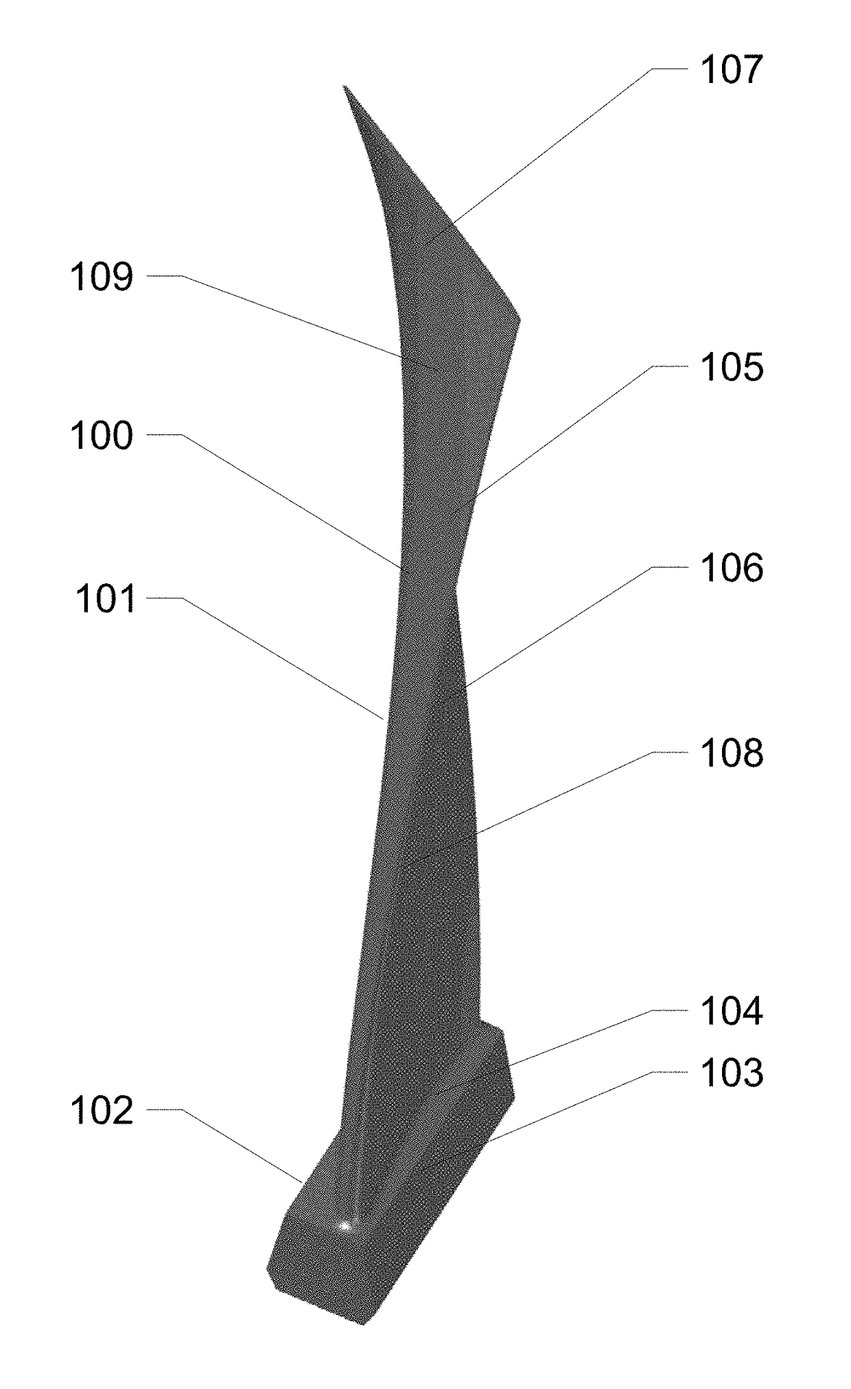
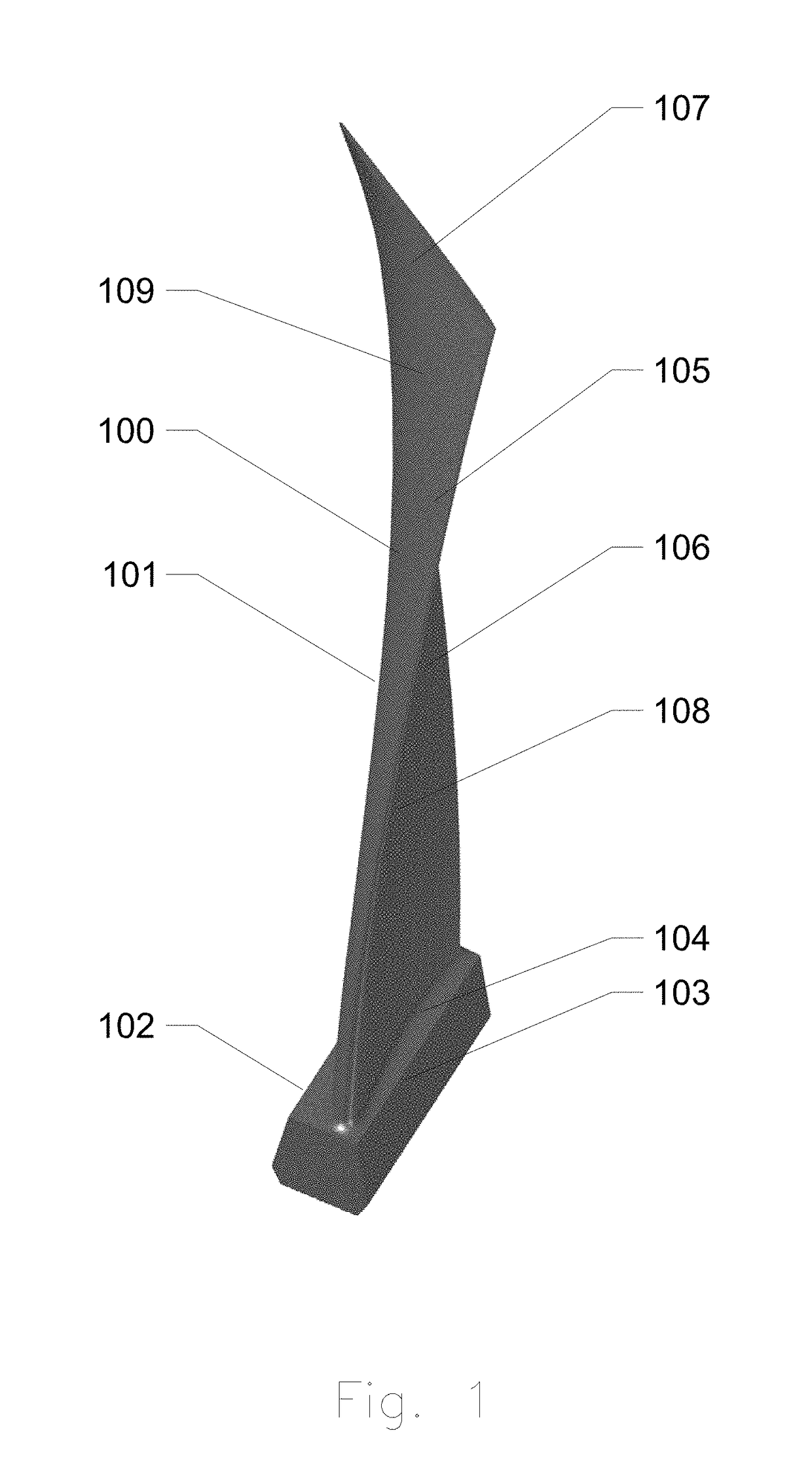
[0048]FIG. 1 shows a blade 100 of a gas turbine engine compressor. The blade is one of the components of the conditioning procedure. Each blade employs a base 101 and an airfoil 102. The base 101 comprises a dovetail root 103 and a platform 104. The airfoil 102 contains a leading edge 105, a trailing edge 106 and a profile tip 107. The airfoil 102 has two sides: concave-pressure side 108 and convex-suction side 109. High velocity air flow across the curved blade and vane profile, particularly on the suction side 109, forms a laminar boundary layer near the leading edge 105, downstream but prior to the trailing edge 106 it develops into a turbulent boundary layer. The nature of changes in the boundary layers through-out the profile, influence proper usage of energy in the compressor.

[0049]The compressor blades are manufactured by...


PUM

PropertyMeasurementUnit
Lengthaaaaaaaaaa
Thicknessaaaaaaaaaa
Surface smoothnessaaaaaaaaaa

Abstract

The present invention relates to a conditioning method of gas turbine engine components (e.g. compressor blades and vanes) for aerodynamic noise reduction. The gas turbine engine components are plasma treated in a high vacuum environment to generally reach a surface roughness (Ra) below 150 nanometers and in some cases below 25 nanometers. Then during the same process the components are coated using either a metallic or ceramic, hard, thin coating ranging from 100 to 3000 nanometers in thickness depending on desired surface smoothness and non-fouling properties. The same treatment combined with a surface relaxation process, which is part of a smoothing process, allows applying even up to 100 micrometers of hard coating without changes to high cycle fatigue properties and overall performance. Improved surface smoothness of the components and enhanced non-adhesiveness of the contaminants advance the quality of the flow through the gas path and compressor aerodynamic noise reduction.

Description

BACKGROUND OF THE INVENTION[0001]The present invention relates to a conditioning method of gas turbine engine components for aerodynamic noise reduction, more particularly a method of reducing the surface roughness of blades and vanes of a turbine engine compressor to a level that allows for a change in air flow characteristics and creates aerodynamic noise reduction.[0002]Gas turbine engines are not only used as aircraft engines but also as aero derivative engines. For example industrial engines extensively used in industrial service, marine and land transportation. Aero and ground-based engines are built with many similar components.[0003]One of the sections of a gas turbine engines is a compressor. The compressor delivers compressed air to a combustion chamber. Fuel mixed with compressed air is burned and transformed into a massive volume of gasses. These gasses expand and flow through the stator and rotor blades of the turbine converting produced energy to its kinetic equivalent...

Claims


Application Information

Patent Timeline
IPC IPC(8): B23P15/02C23C14/14C23C14/08C23C14/02B08B7/00
CPCB23P15/02C23C14/14B08B7/0035C23C14/022C23C14/028C23C14/083C23C14/325F05D2240/30F01D5/00Y02T50/60
Inventor WARZYSZYNSKI, MARIUSZWEBSTER, JONATHAN
Owner ENVAEROSPACE
Features
  • Generate Ideas
  • Intellectual Property
  • Life Sciences
  • Materials
  • Tech Scout
  • Unparalleled Data Quality
  • Higher Quality Content
  • 60% Fewer Hallucinations
Learn More