
Single module, flow-electrode apparatus and method for continous water desalination and ion separation by capacitive deionization

a flowelectrode and capacitive deionization technology, applied in the direction of solid sorbent liquid separation, water/sludge/sewage treatment, cation exchanger, etc., can solve the problems of low water recovery rate, complex and expensive cdi reactor integration, and low energy demand that can still be reduced potentially and other problems, to achieve the effect of improving separation efficiency and reducing energy consumption

Active Publication Date: 2018-05-24
DWI LEIBNIZ INST FUR INTERAKTIVE MATERIALIEN EV
View PDF1 Cites 11 Cited by
  • Summary
  • Abstract
  • Description
  • Claims
  • Application Information

AI Technical Summary

Benefits of technology

The present invention is about a new single module, flow-electrode apparatus and method for continuous water desalination and ion separation by capacitive deionization. The invention solves the problem of high energy demand and low water recoveries of current technologies for seawater desalination. The invention uses a new type of electrodes called "flow electrodes" which can be moved and replaced, which improves the efficiency of the process. The apparatus also includes a new type of membrane called "ion exchange membranes" which further enhances the efficiency of the process. The invention provides a more efficient and cost-effective solution for continuous water desalination and ion separation.

Problems solved by technology

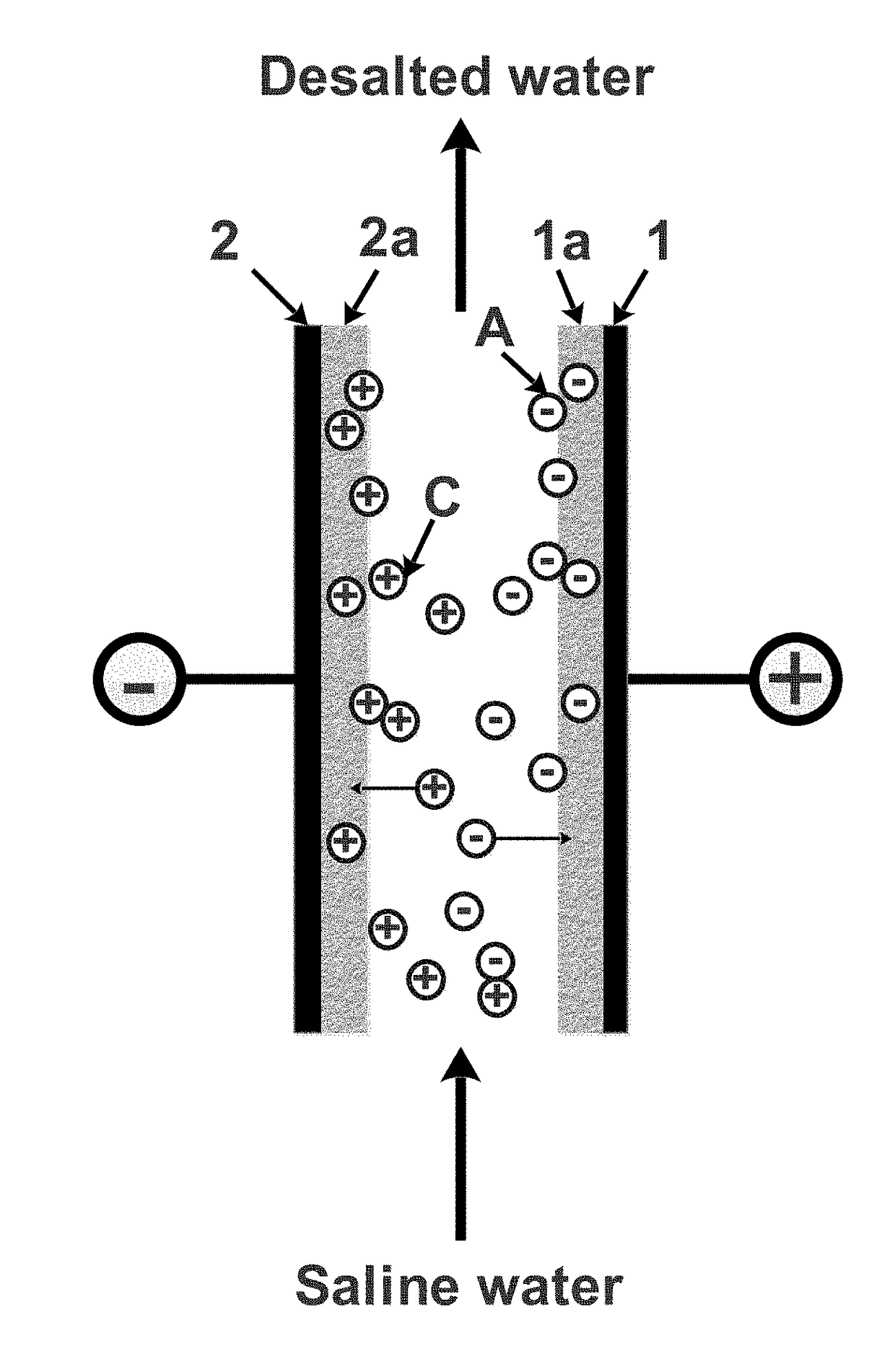
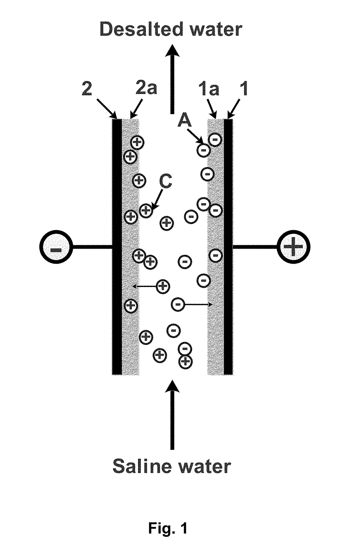
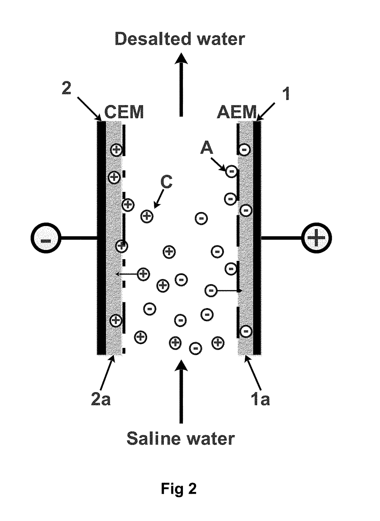
Development of environmentally friendly and energetically efficient technologies for the desalination of water, in particular seawater, is a great challenge for the supply of safe and sufficient water.
Unfortunately, RO has two major drawbacks: an energy demand that still can be reduced potentially and relatively low water recoveries.
The maximum applied potential is limited to a certain value, as higher potentials will result in undesired faradaic processes like electrolytic decomposition of water or electrochemical conversion of dissolved species.
To use the CDI reactor for desalination in cycles of adsorption and regeneration, the CDI reactor needs to be integrated into an intricate and expensive piping, valve and control system.
Their mixing in dead zones of the piping and valve system would annihilate the achieved prior separation and eventually separation efficiency suffers.
It is desirable to avoid such switching processes in the piping system between the adsorption and desorption process, however, a technical solution free of switching between adsorption and desorption cycles is not obvious to the person skilled in the art.
It also requires extensive piping, valves and process control.
However, an economically advantageous continuous operation of a CDI system with stagnant electrodes is very challenging due to the necessity to periodically regenerate the electrodes applied in the CDI process.
Another challenge that modern science has to cope with is a recovery of ionic species from seawater, wastewater, process water and brines for their reuse.
Moreover, finding economically feasible and environmentally friendly removal techniques of certain pollutants from water is a great challenge as well.
In many cases this wastewater cannot be accepted for the treatment in conventional wastewater treatment plants due to extremely high concentrations of nitrogen.
The main challenge that the development of CDI has to cope with is to make the technology feasible for the desalination and selective separation of ionic species from brackish water, seawater, brine streams from chemical processes and alike.
At the current state of the CDI technology with stagnant electrodes, its application is limited due to the relatively low ion adsorption capacity of modern stagnant carbon electrodes (maximum of about 15 mg / g).
High salt concentration as in seawater would require very large amounts of electrode materials and, consequently, large overall reactor volumes are required.
This as well as the use of some of the produced desalinated water hampers the efficacy of the processes disclosed in EP 2 605 326 A2 and WO 2013 / 103236 A1.
Thus, the need of regeneration of the used flow electrodes 4 by mixing and separating from the brine using additional systems reduces the energetic efficiency due to extra pumping, mixing and separation processes, each requiring energy input.
However, the system depicted in FIG. 6 suffers from three serious drawbacks.
First, it requires a second cell causing additional costs.
Second, recirculation of flow electrodes 4 inevitably consumes a lot of energy because slurries have significantly higher viscosities than the particle free solvent alone.
Third, operating two FCDI modules for the desalination process will result in a high volume of the system.

Method used


Image

  • Single module, flow-electrode apparatus and method for continous water desalination and ion separation by capacitive deionization
  • Single module, flow-electrode apparatus and method for continous water desalination and ion separation by capacitive deionization
  • Single module, flow-electrode apparatus and method for continous water desalination and ion separation by capacitive deionization

Examples


example

[0075]In order to further demonstrate the beneficial effects of the apparatus and method according to the present invention, an apparatus for continuous water desalination by capacitive deionization according to the present invention and as shown in FIG. 7 was constructed and operated as follows.

[0076]The first and second current collectors were made of epoxy impregnated graphite plates (supplied by Müller & Rössner GmbH & Co. KG, Troisdorf, Germany) with an engraved flow channel, serving as compartment for the flow electrode, of 3 mm width, 3 mm deep and 189 cm overall length. A fluid containing suspended conductive particles (flow electrode) having a volume of 100 ml and containing 5% (w / v) of activated carbon (Norit® D10, supplied by Cabot Corporation, Alpharetta, Ga., USA) was recirculated between the apparatus and a magnetically stirred storage container at a flow rate of 60 ml / min. Two anion exchange membranes (Fumasep® FAS-PET-130 / ED-100, supplied by FuMA-Tech Gesellschaft fü...


PUM

PropertyMeasurementUnit
thicknessaaaaaaaaaa
ion adsorption capacityaaaaaaaaaa
concentrationaaaaaaaaaa

Abstract

The present invention relates to a single module, flow-electrode apparatus for continuous water desalination, ion separation and selective ion removal and concentration by capacitive deionization, comprising: a first current collector (1), a first compartment (1′) for a flow electrode, a first ion exchange membrane (AEM, CEM), a first liquid-permeable channel (6a) next to the first ion exchange membrane (AEM, CEM), a second ion exchange membrane (CEM, AEM) with a fixed charge opposite to that of the first ion exchange membrane (AEM, CEM) next to the first liquid-permeable channel (6a), a second liquid-permeable channel (6b) next to the second ion exchange membrane (CEM, AEM), a third ion exchange membrane (AEM, CEM) having the same fixed charge as the first ion exchange membrane (AEM, CEM) next to the second liquid-permeable channel (6b), a second compartment (2′) for a flow electrode, and a second current collector (2), wherein a fluid (4) containing suspended conductive particles or a mixture of conductive and non-conductive particles or particles made of a mixture of conductive and non-conductive materials (5) is provided in the first and second compartments (1′, 2′), acting as the flow electrode, as well as a corresponding method.

Description

[0001]The present invention relates to a single module, flow-electrode apparatus and a method for continuous water desalination and ion separation by capacitive deionization.BACKGROUND OF THE INVENTIONCapacitive Deionization for Water Desalination[0002]Development of environmentally friendly and energetically efficient technologies for the desalination of water, in particular seawater, is a great challenge for the supply of safe and sufficient water. Currently, reverse osmosis (RO) is the major technology applied for seawater desalination. Unfortunately, RO has two major drawbacks: an energy demand that still can be reduced potentially and relatively low water recoveries. From a feed water that requires extensive pretreatment only up to 50% is turned into desalinated water while the remaining reject is disposed as concentrated brine.[0003]Electrochemical processes for water desalination are a very attractive alternative to RO. The Capacitive Deionization process (CDI) utilizes the p...

Claims


Application Information

Patent Timeline
Patent Type & Authority Applications(United States)
IPC IPC(8): C02F1/469C02F1/461B01D15/36
CPCC02F1/4691C02F1/46114B01D15/363B01D15/362B01D2325/42C02F2001/46161B01D2325/08C02F2103/08B01D61/428B01D61/463
Inventor WESSLING, MATTHIASGENDEL, YOURIROMMERSKIRCHEN, ALEXANDRA
Owner DWI LEIBNIZ INST FUR INTERAKTIVE MATERIALIEN EV
Learn More