Laser processing machine and laser cutting method

a laser cutting and laser processing machine technology, applied in metal-working equipment, welding equipment, manufacturing tools, etc., can solve the problems of deteriorating cutting surface quality, large size of laser oscillator, high running cost, etc., and achieve the effect of significantly improving the quality of the cutting surfa

Active Publication Date: 2018-06-21
AMADA HLDG CO LTD
View PDF9 Cites 5 Cited by
  • Summary
  • Abstract
  • Description
  • Claims
  • Application Information

AI Technical Summary

Benefits of technology

[0020]In accordance with the laser processing machine and the laser cutting method according to the embodiment, the quality of a cutting surface can be significantly improved compared to the conventional art, even when a laser oscillator that excites a laser beam having a wavelength in a 1 μm band or a shorter wavelength band is used.

Problems solved by technology

A CO2 laser oscillator is large in size and requires high running costs.
On the other hand, in the latter case, the cutting surface roughness deteriorates as the sheet thickness increases.
In addition, in the case where a thick sheet having a sheet thickness of 3 mm or more is cut by a laser processing machine using a fiber laser oscillator or a DDL oscillator, dross is formed and adheres to the sheet metal, and the quality of a cutting surface deteriorates, as an example.
In this way, a fiber laser oscillator or a DDL oscillator is small in size and requires low running costs, but has a defect in that the quality of the cutting surface is not good.
Therefore, in the case where a high-quality cutting surface is required, a fiber laser oscillator or a DDL oscillator cannot be used.

Method used


Image

  • Laser processing machine and laser cutting method
  • Laser processing machine and laser cutting method
  • Laser processing machine and laser cutting method

Examples


Embodiment Construction

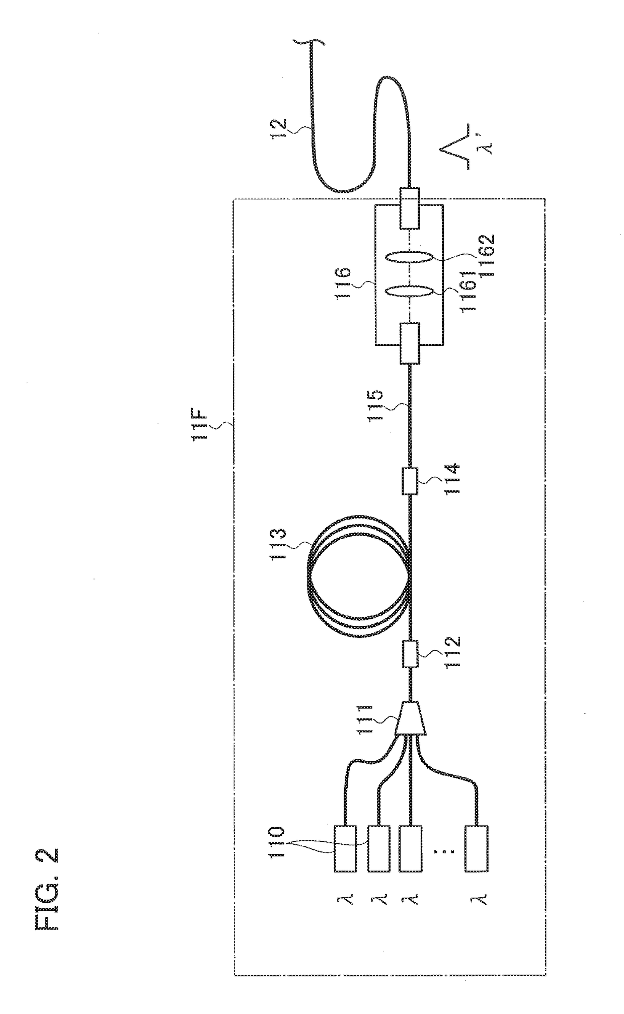
[0037]Hereinafter, a laser processing machine and a laser cutting method according to the embodiment will be described with reference to the accompanying drawings. In the embodiment, a case where a fiber laser oscillator or a DDL oscillator is used as a laser oscillator that excites a laser beam having a wavelength in a 1 μm band or a shorter wavelength band will be described.

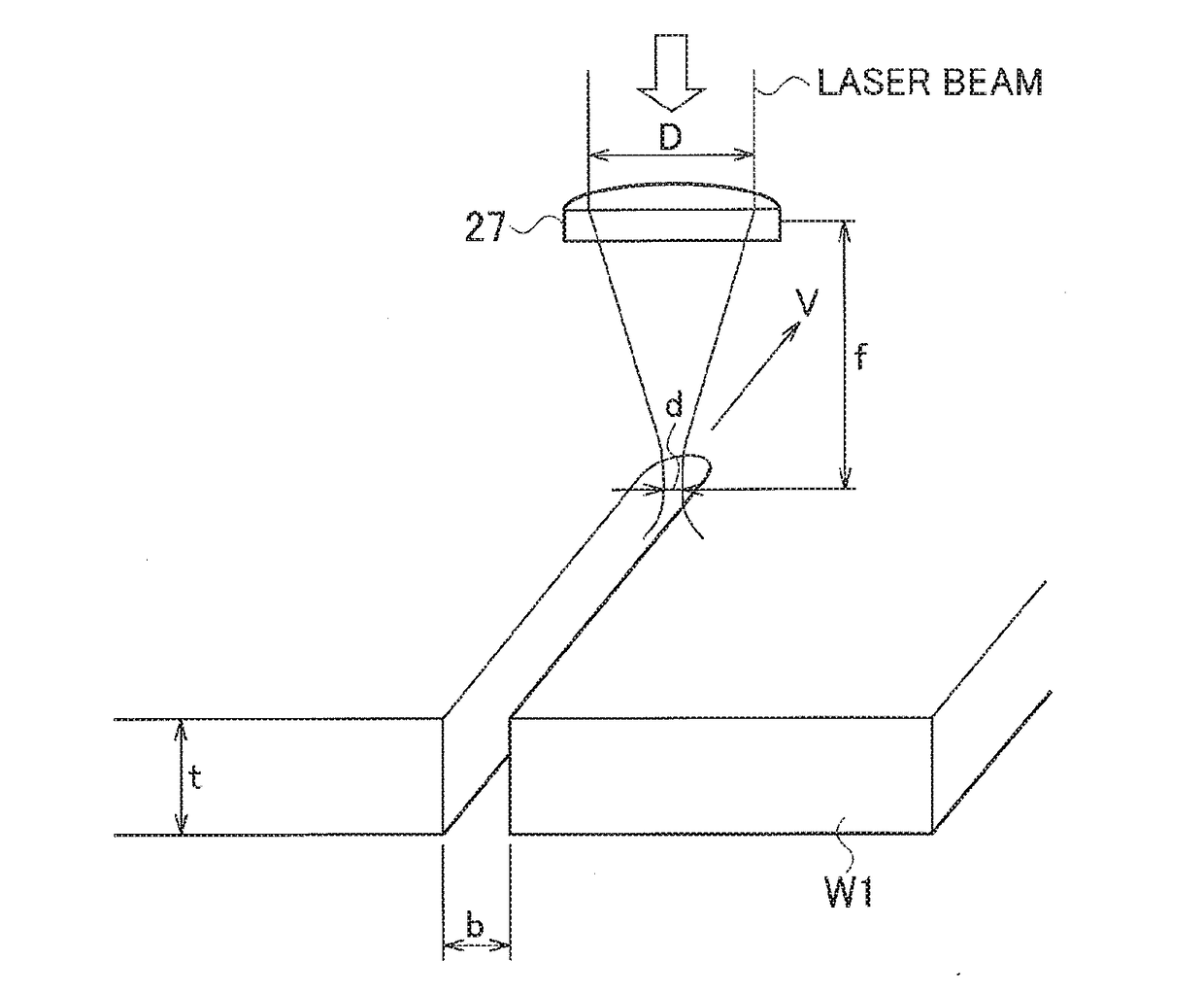
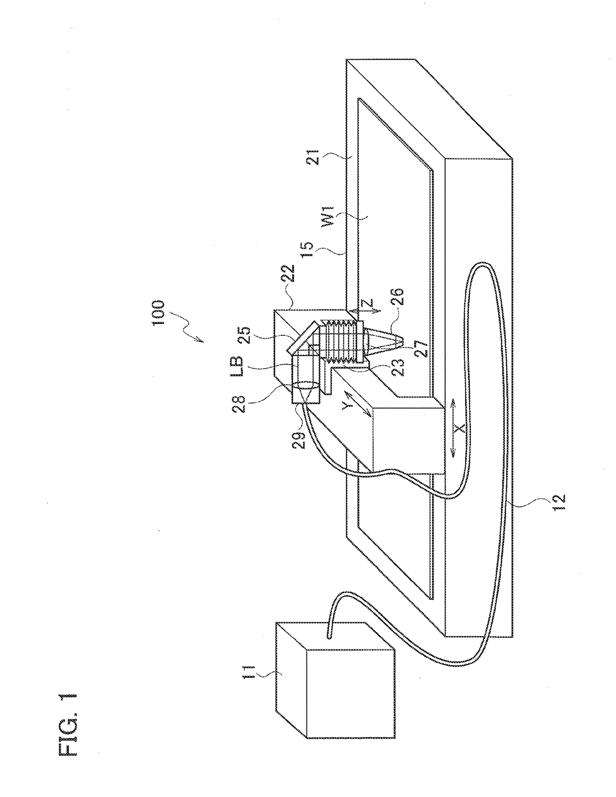
[0038]In FIG. 1, a laser processing machine 100 includes: a laser oscillator 11 that generates and emits a laser beam LB; a laser processing unit 15; and a process fiber 12 that transmits the laser beam LB to the laser processing unit 15. The laser processing machine 100 cuts a sheet metal W1 as a workpiece using the laser beam LB emitted from the laser oscillator 11.

[0039]The laser oscillator 11 is a fiber laser oscillator or a direct diode laser oscillator (hereinafter, referred to as “DDL oscillator”). The process fiber 12 is mounted along cable ducts (not illustrated) of an X-axis and a Y-axis of the laser ...


PUM

PropertyMeasurementUnit
wavelength bandaaaaaaaaaa
radiusaaaaaaaaaa
pressureaaaaaaaaaa

Abstract

A laser processing machine includes a laser oscillator. The laser oscillator excites a laser beam having a wavelength in a 1 μm band or a shorter wavelength band. One process fiber transmits the laser beam emitted from the laser oscillator. A focusing optical element focuses, when a workpiece is irradiated with the laser beam emitted from the process fiber, the laser beam on a plurality of spots in a unit area within a unit time, the unit area having a radius of 0.5 mm of an optical axis of the laser beam, and the unit time being a time from when the workpiece starts to melt to when the melting of the workpiece ends.

Description

TECHNICAL FIELD[0001]The present disclosure relates to a laser processing machine and a laser cutting method.BACKGROUND ART[0002]As a laser oscillator that emits a laser beam with which a laser processing machine cuts a material, various oscillators such as a CO2 laser oscillator, a YAG laser oscillator, a disk laser oscillator, a fiber laser oscillator, or a direct diode laser oscillator (DDL oscillator) can be used.CITATION LISTPatent Literature[PATENT LITERATURE 1] WO 2013 / 058072 A1SUMMARY OF THE INVENTION[0003]A CO2 laser oscillator is large in size and requires high running costs. On the other hand, a fiber laser oscillator or a DDL oscillator is small in size and requires low running costs. Therefore, recently, a fiber laser oscillator or a DDL oscillator has been widely used in a laser processing machine.[0004]In a case where oxide-free cutting is performed on sheet metal (in particular, stainless steel or aluminum) using assist gas such as nitrogen gas, when a case where the...

Claims


Application Information

Patent Timeline
Patent Type & Authority Applications(United States)
IPC IPC(8): B23K26/38B23K26/06B23K26/142
CPCB23K26/38B23K26/0648B23K26/0665B23K26/142B23K26/067B23K26/0676B23K26/08B23K26/064
Inventor SAKO, HIROSHIISHIGURO, HIROAKISUGIYAMA, AKIHIKOMIZOGUCHI, YUYA
Owner AMADA HLDG CO LTD
Why Eureka
Try Eureka