Nanoparticle composite welding filler materials, and methods for producing the same

a composite welding and nanoparticle technology, applied in the field of welding rods, can solve the problems of high-performance alloys that are limited in weldability or joinability, hot cracks generating strength-limiting defects within the final joined structure, and alloys that cannot achieve their full potential as low-cost, high-strength options for engineering applications

Active Publication Date: 2018-08-02
HRL LAB
View PDF2 Cites 23 Cited by
  • Summary
  • Abstract
  • Description
  • Claims
  • Application Information

AI Technical Summary

Benefits of technology

The present invention provides a welding filler material that includes metal or metal alloy particles and nanoparticles chemically and / or physically disposed on the surfaces of the particles. The nanoparticles are consolidated in a three-dimensional architecture throughout the welding filler material. This material can be used as a welding electrode and has improved properties such as improved weld quality and reduced cracking. The nanoparticles can be made from various metals or metal alloys and can be functionalized with other elements such as metals, intermetallic alloys, hydrides, oxides, nitrides, borides, carbides, carbon, and combinations thereof. The welding filler material can be in the form of rods, wires, bars, plates, films, coils, spheres, cubes, prisms, cones, or irregular shapes. The material has a volumetric density of at least 50% of theoretical or at least 90% of theoretical.

Problems solved by technology

However, many high-performance alloys are limited in weldability or joinability due to hot-cracking susceptibility.
Hot cracks generate strength-limiting defects within the final joined structure.
Without the elimination of hot cracking, alloys will not achieve their full potential as a low-cost, high-strength option for engineering applications.
Whereas there are acceptable limits for porosity and inclusions in welds, cracks are almost never acceptable.
Prior art suggests using a variety of different alloys more weldable than the targeted objects to be welded—however, this comes at the cost of material performance.
Welding material performance often suffers from poor strength characteristics in comparison to the target welded structures, due to the inability to use high-performance materials as weld feedstock material.
Previous approaches have incorporated nanoparticles in stir casting, but undesirably without a uniform distribution of reinforcement nanoparticles within the precursor material.
As the metal alloy is subjected to rapid heating, melting, and molten metal circulation, subsequent solidification of certain alloy systems can lead to crack formation as a result of interdendritic shrinkage.
In welding techniques such as laser-beam welding and arc welding, the high cooling rates exacerbate solidification shrinkage and thermal tensions, which place the welded joint under large stress loads that ultimately prevent the production of a defect-free welded object.
However, the resulting weld structure is generally a much weaker composition than the base material.
In addition to that, shifting the composition induces a galvanic couple which can result in corrosion, even in stainless steel—ultimately limiting the effectiveness and quality of the welded part.
Limitations in cost, availability, and performance impede progress towards the successful welding of alloys across several industries.

Method used


Image

  • Nanoparticle composite welding filler materials, and methods for producing the same
  • Nanoparticle composite welding filler materials, and methods for producing the same
  • Nanoparticle composite welding filler materials, and methods for producing the same

Examples


example

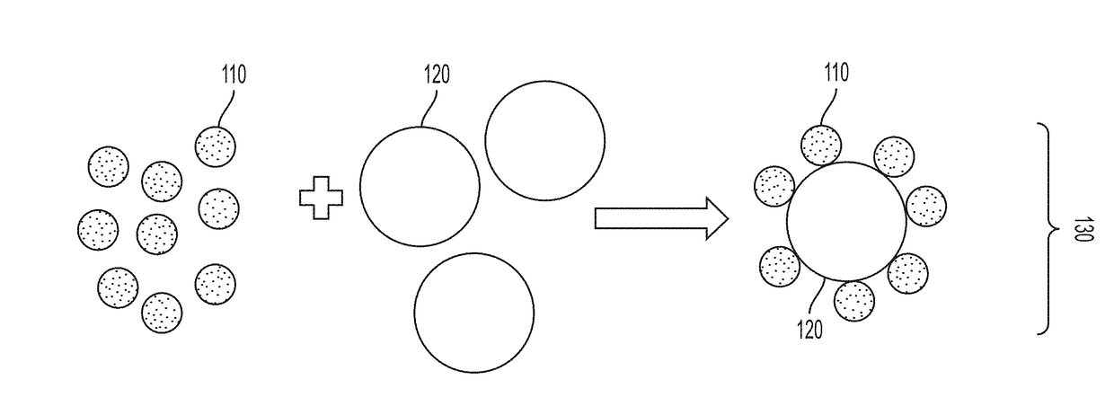
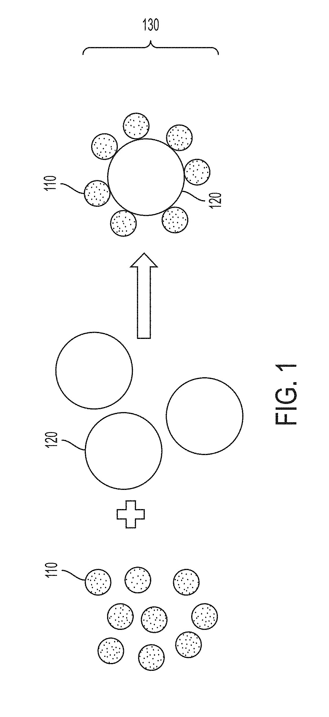
[0224]The effectiveness of this invention (in some variations) is demonstrated in a multipass laser-welded system with aluminum alloy Al 7075 powder as the precursor material combined with ZrH2 nanoparticles.

[0225]Aluminum alloy 7075 micropowder is purchased from Valimet Inc. (Stockton, Calif., U.S.). The powder consists of Al (balance), Zn (5.40%), Mg (2.25%), Cu (1.54%), Cr (0.19%), Fe (0.17%), Si (0.13%), Mn (0.02%), and Ti (2 powder) is purchased from US Research Nanomaterials Inc. (Houston, Tex., U.S.).

[0226]Laser welding is performed on a Concept Laser (Grapevine, Tex., U.S.) M2 selective laser melting machine with single-mode, CW modulated ytterbium fiber laser (1070 nm, 400 W), scan speed up to 7.9 m / s, spot size 50 μm minimum. Powder handling parameters: 80 mm×80 mm build chamber size, 70 mm×70 mm build plate size, 20-80 μm layer thickness. The atmosphere is Ar or N2, 2. Processing is done under a flowing, inert argon atmosphere with oxygen monitoring. All processing is com...


PUM

PropertyMeasurementUnit
Fractionaaaaaaaaaa
Concentrationaaaaaaaaaa
Sizeaaaaaaaaaa

Abstract

A universal approach is described to produce welding filler materials with enhanced grain refining, for making welded objects with hot-crack resistance. Some variations provide a welding filler material comprising a functionalized metal-containing powder, wherein the functionalized metal-containing powder comprises metal or metal alloy particles and a plurality of nanoparticles disposed on surfaces of the metal or metal alloy particles, and wherein the nanoparticles are consolidated in a three-dimensional architecture throughout the welding filler material. A welded object contains a welding filler material comprising the functionalized metal-containing powder, enabling the welded object to be free of hot cracks. Other variations provide methods of making a welding filler material. This approach has been successfully demonstrated by incorporating zirconium-based nanoparticle grain refiners within a welding precursor material for welding aluminum alloy Al 7075, as one non-limiting example.

Description

PRIORITY DATA[0001]This patent application is a non-provisional application with priority to U.S. Provisional Patent App. No. 62 / 452,988, filed on Feb. 1, 2017, which is hereby incorporated by reference herein.FIELD OF THE INVENTION[0002]The present invention generally relates to welding rods or other welding materials, and methods of making and using the same.BACKGROUND OF THE INVENTION[0003]Welding is a fabrication process that joins materials, usually metals or thermoplastics, by causing fusion. Typically, a base metal is melted and a filler material is added to a joint to form a pool of molten material (the weld pool) that cools to form a joint. Pressure may also be used in conjunction with heat, or by itself, to produce a weld.[0004]Some of the known welding methods include oxyacetylene welding; shielded metal arc welding (also known as stick welding or electric welding), which uses an electrode that slowly melts away; tungsten, inert gas (TIG) welding, which uses a non-consuma...

Claims


Application Information

Patent Timeline
IPC IPC(8): B23K35/28B23K35/02B22F1/02B22F1/16B22F1/17
CPCB23K35/286B23K35/0227B22F1/02B23K35/0233B23K35/284B23K35/302B23K35/3033B23K35/3053B23K35/325B23K35/3601B23K35/3602B23K35/3606B23K35/0244B22F2998/10B22F2999/00B22F1/17B22F1/16B22F1/145B22F1/14B22F1/10B22F3/20B22F1/054B22F1/056B22F3/225B22F3/02B22F3/10B22F3/105
Inventor YAHATA, BRENNANMAYER, JUSTINMARTIN, JOHN H.
Owner HRL LAB
Why Eureka
Try Eureka