Method for producing dielectric ceramic, and dielectric ceramic

a technology of dielectric ceramics and dielectric ceramics, applied in ceramics, inorganic insulators, ceramic layered products, etc., can solve the problems of low-resistance wiring of metal components, damage to firing-furnace materials, etc., and achieve the effect of reducing the variation of shrinkage factor, reducing the microstructure, and easy uneven shrinkage factor

Active Publication Date: 2018-08-09
HITACHI METALS LTD
View PDF5 Cites 5 Cited by
  • Summary
  • Abstract
  • Description
  • Claims
  • Application Information

AI Technical Summary

Benefits of technology

[0018]It is preferred in the present invention that before the step of preparing the mixed powder particles, the cordierite material is pulverized to have a particle diameter D95 of 0.5 to 3.0 μm. In the firing, the glass component in the low-temperature-sintering material turns into a liquid phase, so that the microstructure is being densified in such a manner that the liquid is embedded in gaps between the particles of cordierite. When the particle diameter D95 of the cordierite material is within the range described just above, the cordierite material contains no coarse particle, and the densification of the microstructure is uniformly attained. Consequently, before and after the firing, a variation in the shrinkage factor (for example, a variation therein between sites inside a lot, or between lots) of the ceramic substrate can be decreased. This case is more advantageous for attaining the advantageous effects of the invention.
[0019]It is preferred in the present invention that in the step of preparing the mixed powder particles, the mixed powder particles comprise Ag. When the electrode material used for wiring lines is Ag, and the mixed powdery particles do not contain any Ag component, Ag in the electrode is easily diffused into the glass component in the ceramic green sheets at the firing time, so that the microstructure is easily made locally uneven, or the shrinkage factor is easily made uneven. It is presumed that this matter causes the ceramic substrate to be warped. As described above, however, in the mixed-powdery-particles preparing step, the incorporation of Ag into the raw materials restrains the diffusion of Ag into the glass component, so that the ceramic substrate can be restrained from being warped.
[0020]The dielectric ceramic of the present invention comprises, as a main phase thereof, Sr anorthite (SrAl2Si2O8) and further comprises cordierite (2MgO.2Al2O3.5SiO2) and alumina (Al2O3); and has a dielectric constant of 6.5 or less at a frequency of 15 GHz, and a porosity of 0.8% or less. The dielectric ceramic of the invention preferably has an fQ product of 9 THz or more at a frequency of 15 GHz.
[0021]The dielectric ceramic of the present invention is preferably a dielectric ceramic about which a variation in the shrinkage factor (%) of the ceramic is in a range of ±0.15% as a standard deviation 3σ when raw materials of the ceramic are fired. This case enables to decrease a variation in the shrinkage factor (for example, a variation therein between sites inside a lot, or between lots) of the ceramic substrate before and after the firing to densify the microstructure uniformly. This case is more advantageous for attaining the advantageous effects of the invention.
[0022]The dielectric ceramic of the present invention preferably comprises Ag in a proportion of 0.5 to 5% by mass, the proportion being in terms of the proportion of Ag in the composition of (the) raw materials of the ceramic. This case enables to restrain Ag from being diffused into the glass component at the firing time even when Ag is used as the electrode metal used for the wiring lines, so as to restrain the microstructure from being locally and unevenly densified. Consequently, the ceramic substrate can be restrained from being warped while maintaining a target low dielectric constant.
[0023]The dielectric ceramic of the present invention preferably comprises Al2O3 in a proportion of 20 to 25% by mass, SiO2 in one of 50 to 60% by mass, SrCO3 in one of 9 to 16% by mass, MgO in one of 3 to 6% by mass, Bi2O3 in one of 2 to 4% by mass, Na2CO3 in one of 1.5 to 5% by mass, K2CO3 in one of 0 to 1.0% by mass, CuO in one of 0.2 to 0.4% by mass, and Mn3O4 in one of 0.4 to 0.7% by mass, when the whole of Al2O3, SiO2, SrCO3, MgO, Bi2O3, Na2CO3, K2CO3, CuO, and Mn3O4 is 100% by mass, each of the proportions being in terms of the proportion of the corresponding oxide or carbonate in the composition of the raw materials.

Problems solved by technology

However, W, Mo or the like is large in electric resistivity and in loss in a high-frequency range, so that the metal is not usable for components for which low-resistance wiring is required, or components for high frequencies.
However, the inorganic composition may cause, in a producing process thereof, for example, inconveniences that a B (boron) compound included in borosilicate based glass damages firing-furnace material, and that in the process of producing the inorganic composition into a ceramic sheet, the B compound is dissolved in water or alcohol and this compound segregates when the resultant workpiece is dried.

Method used


Image

  • Method for producing dielectric ceramic, and dielectric ceramic
  • Method for producing dielectric ceramic, and dielectric ceramic
  • Method for producing dielectric ceramic, and dielectric ceramic

Examples


example 1

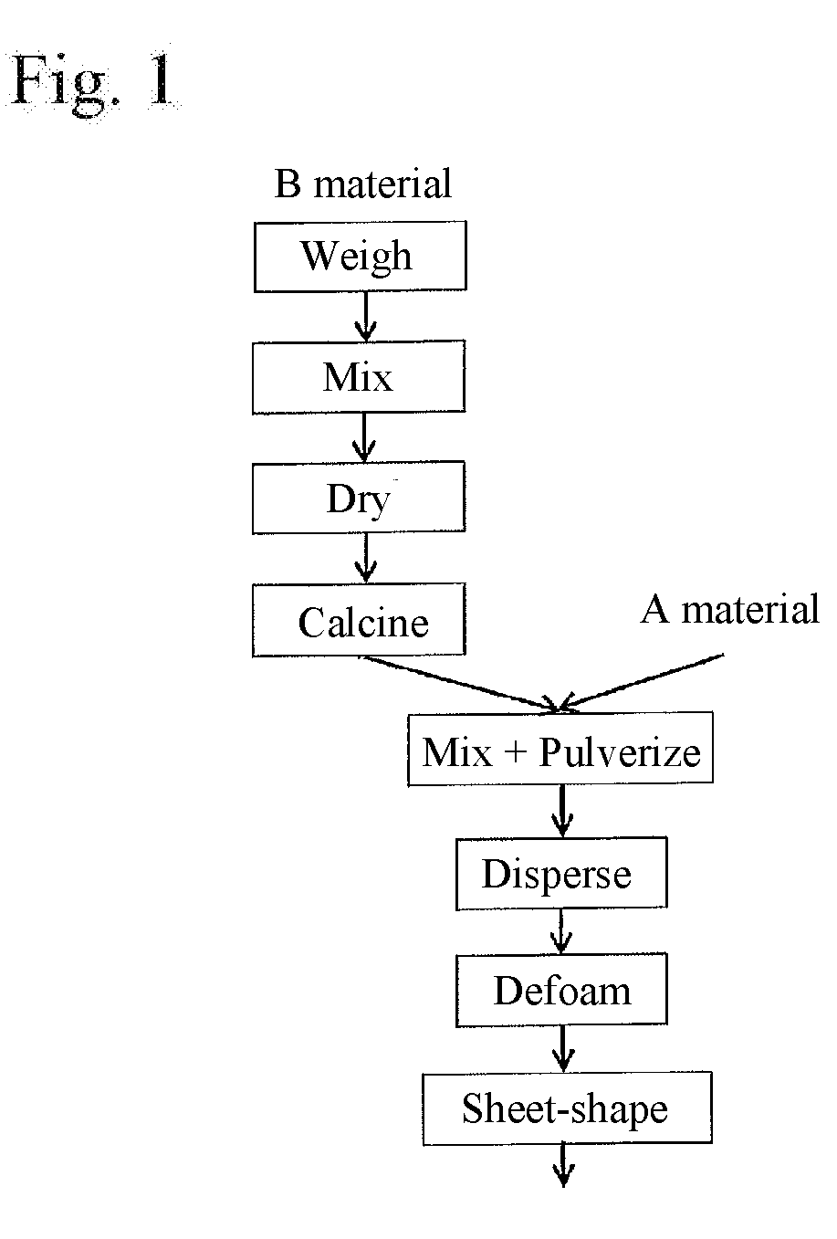
[0105]In accordance with the flowchart in FIG. 1, a dielectric ceramic was produced. [0091]

(Preparation of Cordierite Material (A Material))

[0106]As an A material, the following was used: a commercially available cordierite material (composition: 2MgO.2Al2O3.5SiO2; purity: 97.5%; median diameter D50: 1.65 μm, and BET: 6.3 m2 / g.

(Production of Low-Temperature-Sintering Material (B Material))

[0107]Raw materials as shown in Table 1 shown below were used as raw materials of a low-temperature-sintering material. These materials were weighed to have a composition shown in Table 2 and give a total weight of 50 kg.

TABLE 1Raw materialsPurity (%)Median dimeter D50 (μm)BET (m2 / g)Al2O399.90.556.5SiO295.4—41.5SrCO399.50.427.50Bi2O399.20.832.38K2CO399.9—0.36Na2CO399.5—1.92CuO99.54.800.75Mn3O491.0—20.3

TABLE 2Main components(100 parts by mass)Secondary componentsAl2O3SiO2SrCO3Bi2O3Na2CO3K2CO3CuOMn3O4(parts by(parts by(parts by(parts by(parts by(parts by(part by(part bymass)mass)mass)mass)mass)mass)m...

example 2

[0119]In the same way as in Example 1 except the ratio by content between the low-temperature-sintering material (B material) and the cordierite material (A material), mixed powdery particles were yielded (72.5% by mass of the low-temperature-sintering material (B material) and 27.5% by mass of the cordierite material (A material)). A slurry of the mixed powdery particles was taken out. To 100 parts by mass of the slurry were initially added 7 parts by mass of a plasticizer (DOP), and then thereto were added 10 parts by mass of a binder (PVB). The materials were stirred and dispersed (at a rotating number of 270 rpm). Furthermore, the resultant was vacuum-degassed to be defoamed. In this way, entrained air, the organic solvent and other volatile components were evaporated to make the resultant into a slurry state that the viscosity was adjusted to 8500 cP. A doctor blade method was used to shape the defoamed slurry into a ceramic green sheet having a shaping thickness of 150 μm at a...

examples 3 and 4

[0123]A dielectric ceramic of Example 3 was yielded in the same way as in Example 2 except the use of the mixed powdery particles produced in Example 1 (70.0% by mass of the low-temperature-sintering material (B material) and 30.0% by mass of the cordierite material (A material)). Moreover, a dielectric ceramic of Example 4 was yielded in the same way as in Example 2 except the use of mixed powdery particles (67.5% by mass of the low-temperature-sintering material (B material) and 32.5% by mass of the cordierite material (A material)).

Comparative Examples 3, 4, 5 and 6

[0124]A method for producing a dielectric ceramic of each of Comparative Examples 3 to 6 is as shown in a flowchart in FIG. 9. Specifically, in the same way as in Comparative Example 1, a low-temperature-sintering material (B material) was produced. Subsequently, a pulverizing and a drying step were added to the process before the B material was mixed with the cordierite material (A material). In Comparative Example 5,...


PUM

PropertyMeasurementUnit
median diameter D50aaaaaaaaaa
porosityaaaaaaaaaa
frequencyaaaaaaaaaa

Abstract

A method for producing a dielectric ceramic includes: shaping mixed powdery particles including a cordierite material (2MgO.2Al2O3.5SiO2) and a low-temperature-sintering material including Al, Si and Sr, the Si being partially vitrified; and firing the resultant shaped body. The method includes the step of wet-pulverizing the low-temperature-sintering material together with at least the cordierite material to prepare mixed powder particles having a median diameter D50 less than 1 μm; and, in a process until a time of the preparation of the mixed powder particles, the low-temperature-sintering material undergoes no step of wet-pulverizing only the low-temperature-sintering material, and drying the resultant pulverized material.

Description

TECHNICAL FIELD[0001]The present invention relates to a method for producing a dielectric ceramic used in a ceramic substrate configured in an electric component in a microwave band, and a dielectric ceramic.BACKGROUND ART[0002]In recent years, semiconductor LSIs, chip components, and others have been increasingly made smaller in size and lower in stature, and the pitch between terminals has been increasingly made narrower. Ceramic substrates on which these members are to be mounted have also been required, for example, to be made smaller in size and lower in stature, and be made higher in precision. Hitherto, as a dielectric ceramic configured in a ceramic substrate, alumina has been mainly used. The firing temperature of alumina is as high as a temperature of 1300 to 1600° C.; thus, a high melting point metal such as W or Mo is used for the material of electrodes used in wiring lines, such as transmission line paths, on a ceramic substrate. However, W, Mo or the like is large in e...

Claims


Application Information

Patent Timeline
Patent Type & Authority Applications(United States)
IPC IPC(8): C04B35/195C04B35/63H01B3/12
CPCC04B35/195C04B35/6303H01B3/12C04B2235/3217B32B18/00C04B35/6261C04B35/6263C04B35/6264C04B35/62655C04B35/62675C04B35/62685C04B35/62695C04B2235/3201C04B2235/3206C04B2235/3213C04B2235/3263C04B2235/3281C04B2235/3298C04B2235/3418C04B2235/3481C04B2235/408C04B2235/5409C04B2235/5436C04B2235/5445C04B2235/5481C04B2235/6025C04B2235/604C04B2235/656C04B2235/6562C04B2235/77C04B2235/80C04B2235/9615C04B2237/341C04B2237/62C04B2237/66C04B35/626C04B35/63
Inventor NAKAJIMA, HIROKAZU
Owner HITACHI METALS LTD
Why Eureka
Try Eureka