

A method of producing a two-dimensional material
a two-dimensional material and production method technology, applied in the direction of polycrystalline material growth, crystal growth process, silicon compound, etc., can solve the problems of inability to achieve the aforementioned properties, the mechanical strength of the graphene sheet is sufficiently increased, and the performance properties of the device application of graphene have not yet been realized, etc., to achieve the effect of increasing the mean grain size and sufficient mechanical strength of the graphene sh
- Summary
- Abstract
- Description
- Claims
- Application Information
AI Technical Summary
Benefits of technology
Problems solved by technology
Method used
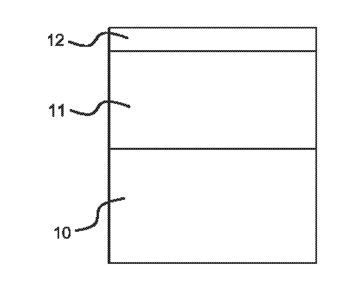
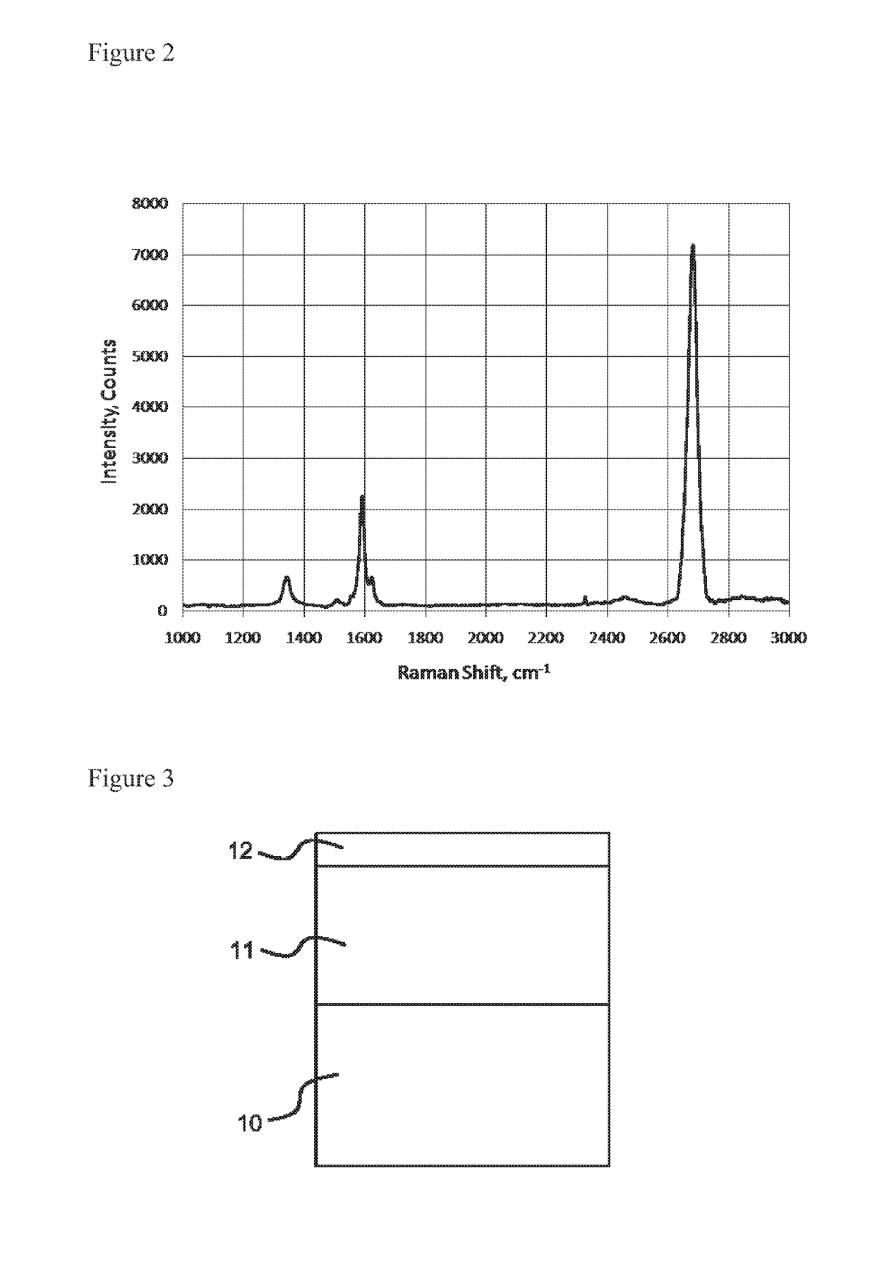
Image

Examples
example 1
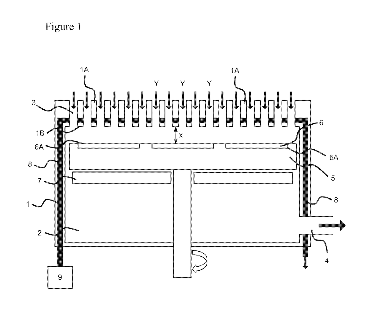
[0150]Graphene monolayer(s) can be produced on a selected substrate within the standard operating parameters of a close coupled reaction chamber via VPE. With careful selection of the graphene precursor and substrate type and matching with suitable reaction chamber parameters it is possible to deposit graphene on the substrate surface.
[0151]For example, selecting a metallocene, Cp2Mg or Cp2Fe as a process precursor the reactor is heated to a temperature such that the surface of the substrate (here silicon or sapphire) is greater than the required, or complete, decomposition temperature of the precursor, here >500° C. The reactor pressure is lowered to suitable vacuum level to ensure evacuation of unwanted process by-products, for the metallocenes in this example a pressure of <200 mbar has proven successful. The metallocene and a dilution flow of hydrogen are then introduced to the reactor, through the inlets, and hence substrate surface at a suitable flow rate, in this example 700 ...
example 2
[0153]Graphene monolayer(s) production using CH3Br as a process precursor. The reactor is heated to a temperature such that the substrate, here sapphire, is greater than the complete decomposition temperature of the precursor, here >350° C. The reactor pressure is lowered to a suitable vacuum level to ensure evacuation of unwanted decomposition and reaction by-products and also facilitate high enough residency time of carbon products at the substrate surface to form graphene. For CH3Br a pressure of 600 mbar has been proven ideal, as the main unwanted by-product Br has vapor pressure higher than this at the selected deposition temperature. The precursor and a dilution flow of nitrogen gas are then introduced to the reactor and hence substrate, through the chamber inlets, at a suitable flow rate, in this example 1000 sccm is ideal for CH3Br and 2000 sccm for nitrogen. Nitrogen is used in this process so as to limit the possible formation of HBr. The precursor and dilution gas flow th...
example 3
[0154]Graphene monolayer(s) production using CH4 as a process precursor. The reactor is heated to a temperature such that the substrate, here sapphire, is greater than the initial decomposition temperature of the precursor, here >1100° C. The reactor pressure is set to a suitable vacuum level to ensure favorable gas velocity near the substrate surface, for CH4 a pressure of 800-900 mbar is suitable as the by-products of CH4 decomposition will not adversely affect the growing material, the advantage here is the increased residency time of precursor material, at higher reactor pressure, promotes high deposition rates, significantly shortening the time required to deposit graphene. The precursor and a dilution gas of hydrogen are then introduced to the reactor and hence substrate surface, through the chamber inlets, at a suitable flow rate, in this example 1000 sccm is ideal for the CH4 and 2000 sccm for the hydrogen. The precursor flows across the substrate surface for a period of tim...
PUM
| Property | Measurement | Unit |
|---|---|---|
| Distance | aaaaa | aaaaa |
| Distance | aaaaa | aaaaa |
| Distance | aaaaa | aaaaa |
Abstract
Description
Claims
Application Information