Metal Nanostructure and Method for Manufacturing Thereof

Active Publication Date: 2018-11-01
LG DISPLAY CO LTD +1
View PDF1 Cites 9 Cited by
  • Summary
  • Abstract
  • Description
  • Claims
  • Application Information

AI Technical Summary

Benefits of technology

[0020]According to the present disclosure, the present disclosure may provide a manufacturing method which is capable of synthesizing a novel chiral metal nanostructure having a high optical acti

Problems solved by technology

However, according to the technique of the related art, a time and a manufacturing cost are high and a yield is low so that it is not appropriate for mass production and it is very restrictive to implement and adjust optical characteristic in a visible light region.
However, the electron beam lithography method is very costly and cannot be applied for mass production.
However, the direct laser writing method and the glancing angle deposition method are very costly and cannot be applied for mass production.
However, according to this method, it is difficult to manufactu

Method used


Image

  • Metal Nanostructure and Method for Manufacturing Thereof
  • Metal Nanostructure and Method for Manufacturing Thereof
  • Metal Nanostructure and Method for Manufacturing Thereof

Examples


Example

Example 1

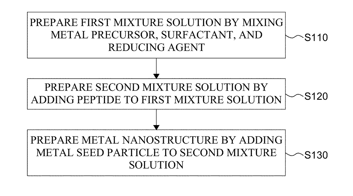
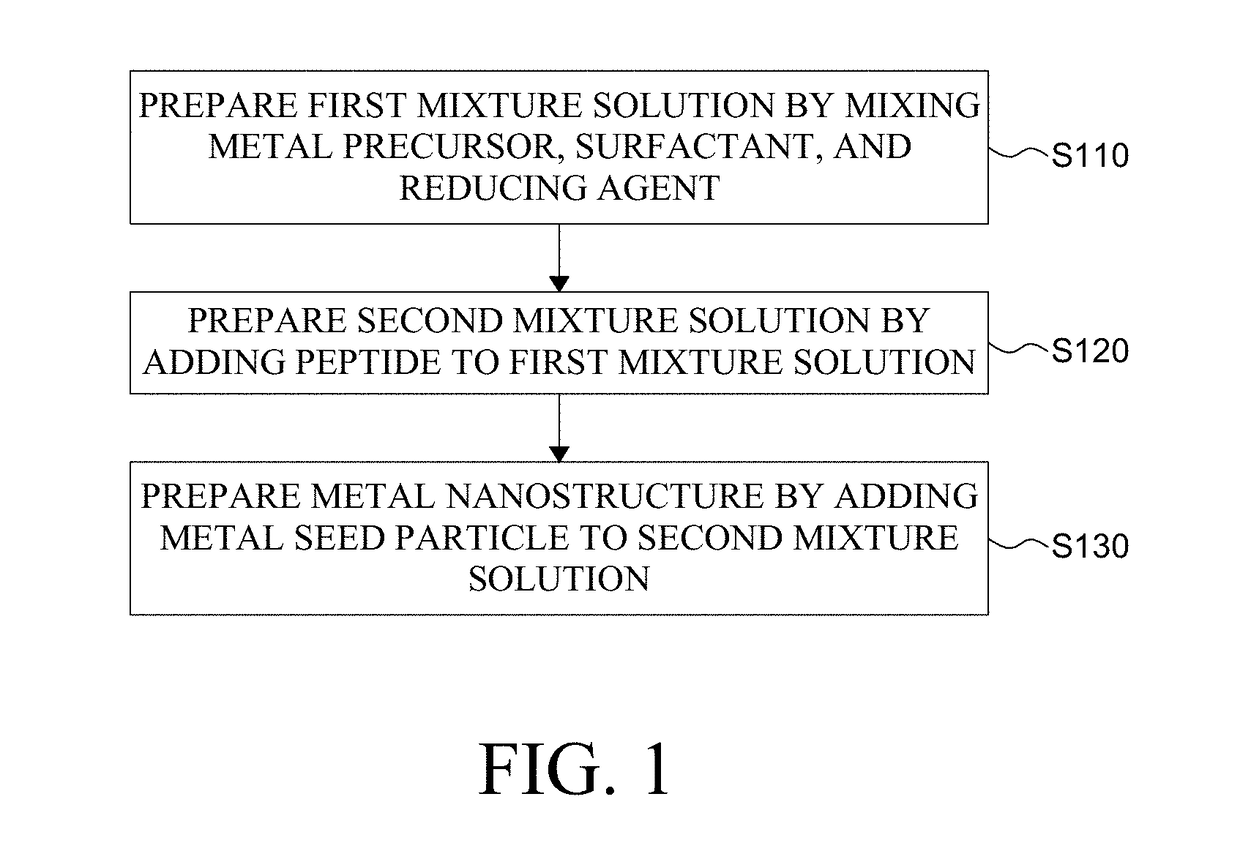
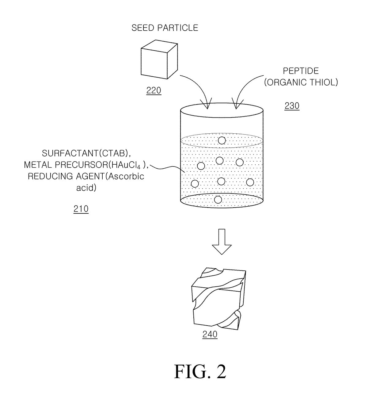
[0073]0.8 mL of hexadecyltrimethylammonium bromide (CTAB) which was a surfactant having a concentration of 100 mM was added into 3.95 mL of water. 0.1 mL of 10 mM tetrachloroauric (III) trihydrate (HAuCl43H2O) which was a gold precursor and 0.475 mL of 0.1 M L-ascorbic acid which was a reducing agent were mixed with the above solution and then blended by a vortex mixer for one minute to prepare a first mixture solution. 0.5 μL of 1 mM L-cysteine dissolved in water was added to the prepared first mixture solution 210, and then blended by the vortex mixer for 1 minute to prepare a second mixture solution 210. The growth started by adding a cube nanoparticle 220 having a size of 45 nm to the second mixture solution 210 and then two hours later, a metal nanostructure 240 having a chiral structure controlled by the L-cysteine was synthesized. Thereafter, the resulting metal nanostructure was washed and separated through centrifugation (5000 rpm for 30 seconds).

[0074]The method f...

Example

Example 2

[0091]The chiral metal nanostructure was prepared by the same method as Example 1 except that L-glutathione was used instead of L-cysteine.

[0092]FIGS. 4A to 4D are schematic diagrams and SEM images for explaining a process of forming a chiral metal nanostructure according to Example 2. FIG. 4A is an SEM image of a chiral metal nanostructure prepared by Example 2. FIGS. 4B and 4C are a schematic diagram and an SEM image seen from {110} and {100} directions for explaining a behavior of a hexoctahedron metal particle surface which is an intermediate in the presence of L-glutathione. FIG. 4D is a schematic diagram and an SEM image for explaining a structure of a chiral metal nanostructure prepared by Example 2. The shape and the surface of the metal seed particles are the same as those described with reference to FIGS. 3A to 3D, so that a specific description will be omitted.

[0093]Referring to FIGS. 4B and 4C, L-glutathione is mainly adsorbed in the R region of the hexoctahedro...

Example

Example 3

[0104]The chiral metal nanostructure was prepared by the same method as Example 1 except that D-cysteine was used instead of L-cysteine.

[0105]FIG. 7A is an SEM image of a chiral metal nanostructure prepared by Example 1. FIG. 7B is an SEM image of a chiral metal nanostructure prepared by Example 3.

[0106]Referring to FIG. 7A, the chiral metal nanostructure formed using L-cysteine had a twisted corner. Specifically, the chiral metal nanostructure illustrated in FIG. 7A had a corner m which was rotated by −φ degree from a straight line n obtained by connecting vertexes. Differently from this, the chiral metal nanostructure illustrated in FIG. 7B had a corner m′ which was rotated by +φ degree from a straight line n′ obtained by connecting vertexes. That is, it was confirmed that the chiral metal nanostructure prepared using L-cysteine and the chiral metal nanostructure prepared using D-cysteine had chiral structures which rotate in opposite directions.

[0107]FIG. 7C is a graph i...


PUM

PropertyMeasurementUnit
Sizeaaaaaaaaaa
Sizeaaaaaaaaaa
Particle sizeaaaaaaaaaa

Abstract

The present disclosure relates to a method for manufacturing a metal nanostructure having a chiral structure. The method for manufacturing a metal nanostructure comprises: preparing a first mixture solution by mixing a metal precursor, a surfactant, and a reducing agent; preparing a second mixture solution by adding a peptide to the first mixture solution; and preparing a metal nanostructure having a chiral structure by adding a metal seed particle to the second mixture solution.

Description

CROSS-REFERENCE TO RELATED APPLICATIONS[0001]This application claims the priority of U.S. Provisional Application No. 62 / 491,825 filed on Apr. 28, 2017, in the United States Patents and Trademark Office, the disclosure of which is incorporated herein by reference in its entirety.BACKGROUNDField[0002]The present disclosure relates to a metal nanostructure and a manufacturing method thereof, and more particularly, to a method for manufacturing a metal nanostructure having a chirality.Description of the Related Art[0003]A chiral structure refers to a material having a three-dimensional chiral structure. The three-dimensional chiral structure is not limited thereto, but it means an asymmetric structure which is twisted in one direction. Therefore, the chiral structure has a structure which is grown to be bent in one direction.[0004]The chiral structure may be formed by an organic or inorganic compound or may be formed by a metal compound.[0005]A method for creating chiral structures of ...

Claims


Application Information

Patent Timeline
IPC IPC(8): C08G73/02B22F1/054
CPCC08G73/0206B82Y30/00B82Y20/00B82Y40/00C07K5/0215C07K5/06026C07K5/06165B22F9/24B22F1/0553B22F1/054B22F1/056B22F1/07C30B7/14Y10S977/895
Inventor CHANG, KISEOKKIM, WOOKSUNGNAM, KITAERYU, SUNGPILLEE, HYEEUNAHN, HYOYONG
Owner LG DISPLAY CO LTD
Why Eureka
Try Eureka