
1D-CNN-Based Distributed Optical Fiber Sensing Signal Feature Learning and Classification Method

a distributed optical fiber and signal feature technology, applied in the field of 1dcnnbased distributed optical fiber sensing signal feature learning and classification methods, can solve the problems of preventing the industry from being mature, restricting the progression of its large-scale application, and facing complex extensive monitoring environments, so as to improve the identification effect, improve the identification accuracy, and improve the accuracy of algorithm update speed

Active Publication Date: 2018-12-13
UNIV OF ELECTRONICS SCI & TECH OF CHINA
View PDF1 Cites 148 Cited by
  • Summary
  • Abstract
  • Description
  • Claims
  • Application Information

AI Technical Summary

Benefits of technology

The present invention is a system for identifying and classifying different types of events using data collected from distributed optical fiber sensors. The invention has three technical solutions: 1. A large event database is built using a deep convolution neural network, which is trained and optimized to extract typical event signal features along a distributed optical fiber. This database is used to identify and classify various types of events with high accuracy and quickly. 2. When the event object to be analyzed is one-dimensional acoustic or vibration sensing signals, a special design is used for identifying and classifying these signals. This is because existing methods for identifying one-dimensional signals require time-frequency transformation and may have higher computational complexity. The present invention reduces computational complexity and improves learning effect by using a one-dimensional convolution neural network structure. 3. The present invention automates the learning and fast extraction of distinguishable features of typical events in complex and changing environment conditions. The learning process is performed through a deep learning process using a convolution neural network, and the network is trained to identify and classify sensing signals at each spatial point in the entire monitoring range. This prevents the need for adjusting parameters caused by direct adoption of the network for classification and ensures optimal classification performance.

Problems solved by technology

However, a certain gap exists at the levels of onsite data analysis and processing, data mining, depth of understanding and application software, preventing the industry from being mature and restricting the progression of its large-scale application.
Although the quantitative or qualitative analysis of single point sensing data is not difficult, its large-scale networking brings serious challenges such as the analysis, processing and deep mining of big data generated from monitoring in extensive complex environments, which become a common problem in the current optical fiber sensing field.
For existing distributed optical fiber acoustic and vibration sensing systems based on phase demodulation, they face complex extensive monitoring environments in actual application and particularly face varied burial environments at different sections or points.
The current local observation and processing models and classification methods fail to consider the difference and complexity of network node distribution environments, and the algorithm has poor adaptive ability and generalization ability when facing complex environments; the traditional manual method for feature extraction and pattern identification cannot follow the data updating speed and changing mode of massive data, resulting in poor onsite intelligent detection and identification ability of the system in extensive monitoring, slightly high overall false alarm rate and insufficient intelligence level, and thus is unable to meet actual application requirements.

Method used


Image

  • 1D-CNN-Based Distributed Optical Fiber Sensing Signal Feature Learning and Classification Method
  • 1D-CNN-Based Distributed Optical Fiber Sensing Signal Feature Learning and Classification Method
  • 1D-CNN-Based Distributed Optical Fiber Sensing Signal Feature Learning and Classification Method

Examples


first preferred embodiment

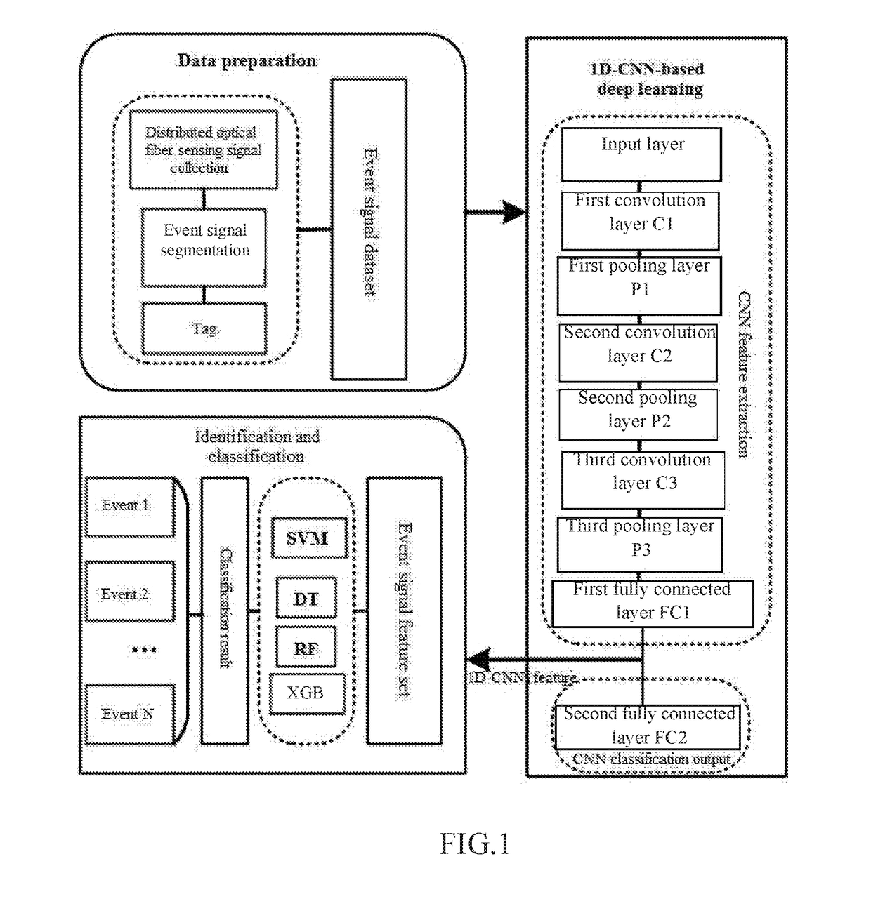
[0067]Take the application of the distributed optical fiber acoustic and vibration sensing signal feature learning and classification method based on a one-dimensional conventional neural network (1D-CNN) in long-distance pipeline safety monitoring for instance. As shown in FIG. 1, the whole signal processing flow is mainly divided into three parts.

[0068]Part 1: Data Preparation

[0069]Acoustic or vibration signals (i.e. distributed optical fiber sensing signals) along the pipeline against complex background environment of actual application site are collected with the distributed optical fiber acoustic and vibration sensing system hardware based on the phase-sensitive optical time domain reflectometer, time sequences of the pipeline event signals collected at all spatial points by the time period are segmented, and a typical event signal dataset is constructed.

[0070]Part 2: Constructing a One-Dimensional Conventional Neural Network and Conducting Deep Learning and Feature Extraction ...

second preferred embodiment

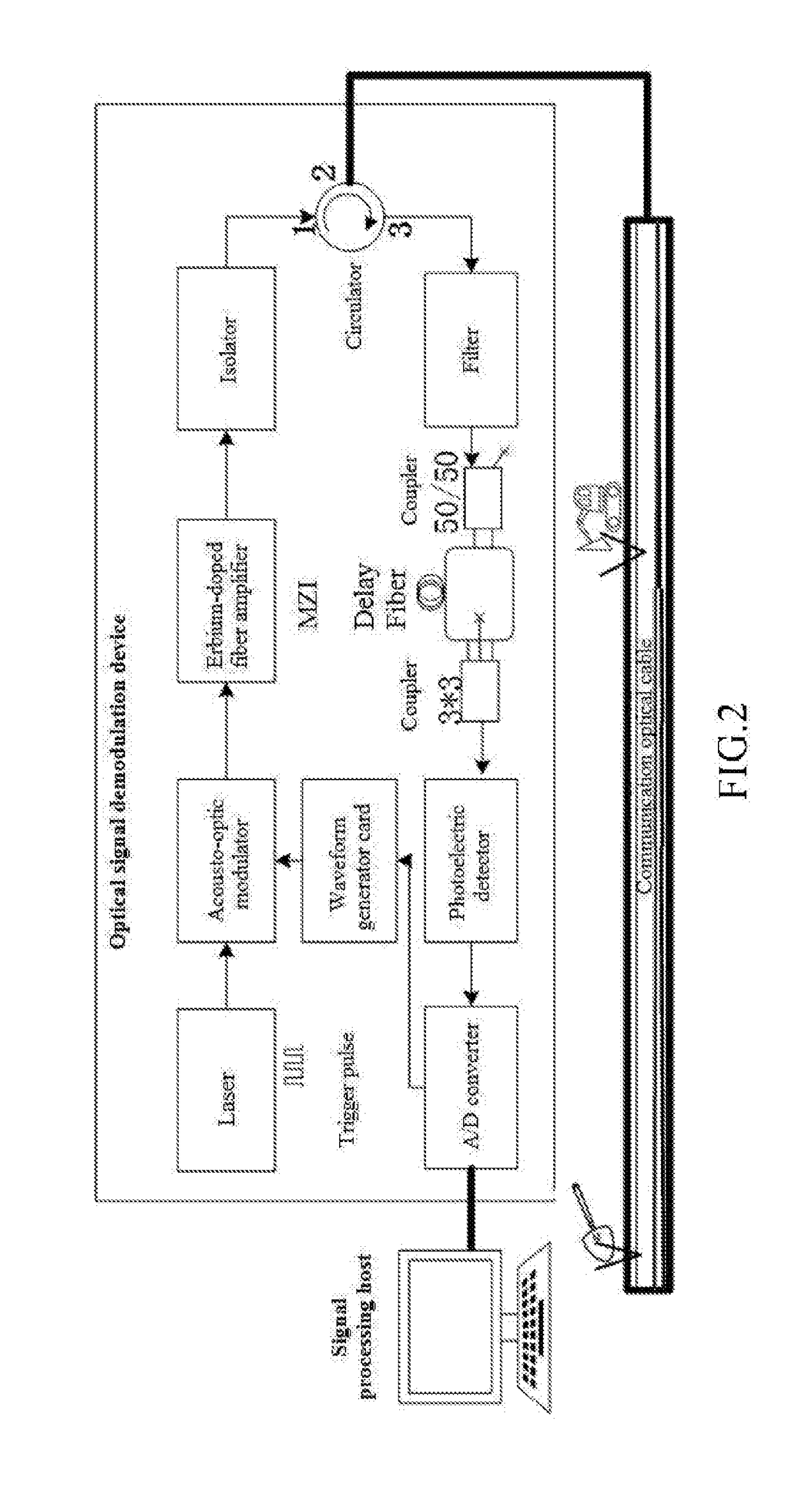
[0074]The system hardware for signal collection in the first preferred embodiment is a distributed optical fiber acoustic and vibration sensing system with phase-sensitive optical time domain reflectometry (Φ-OTDR) based on phase demodulation, and the structure and the working principle of the system are shown in FIG. 2. The system hardware is composed of three parts, namely optical detection cable, optical signal demodulation equipment and signal processing host. The optical detection cable is usually a common single-mode communication optical fiber and is generally laid and buried along underground pipelines, power transmission cables or city roads; alternatively, unoccupied fiber cores of communication optical cables laid along pipelines or roads can be directly utilized. The optical signal demodulation equipment is the core of the system, and the internal components mainly include optical devices and electrical devices. One path of continuous coherent optical signals is generate...

third preferred embodiment

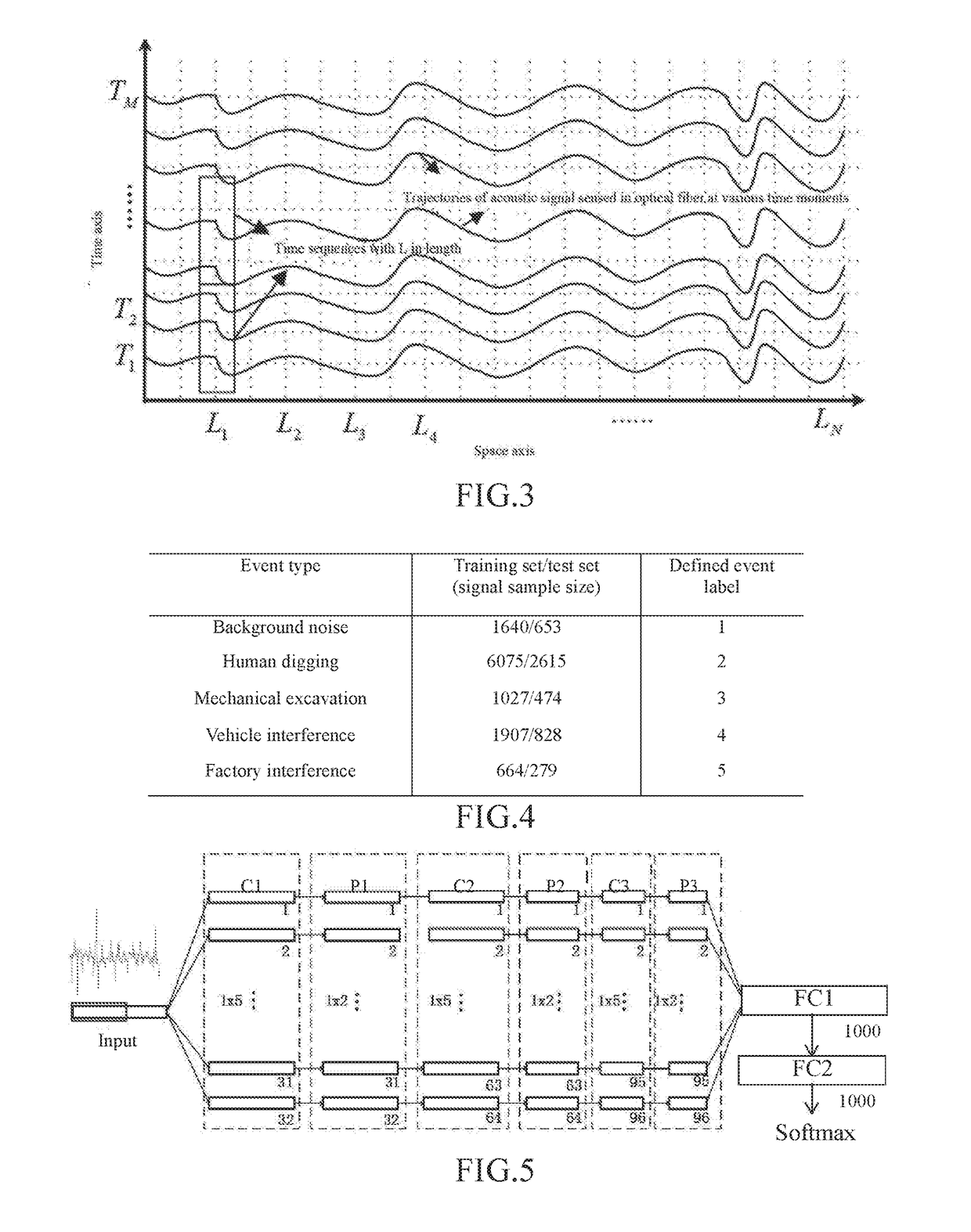
[0077]Event signals in rows along the time axis are segmented according to the one-dimensional time sequences at each spatial point in the spatial-temporal response signal matrix accumulated in the second preferred embodiment, and a typical event signal dataset raw_data is constructed. In the present invention, a pipeline safety related typical event signal dataset raw_data is constructed by taking pipeline safety monitoring as an example. The specific operating process comprises steps of: successively intercepting event signals with time length L against the signal time sequences at each spatial point, as shown in the rectangular frame part of FIG. 3, taking the event signals as event signal samples, denoted as X1, X2 . . . , and respectively attaching labels according to actual event types.

[0078]During pipeline safety monitoring, typical event types usually include: stationary environmental noise, human digging, mechanical excavation, vehicle interference and factory interference ...


PUM


Abstract

A 1D-CNN-based ((one-dimensional convolutional neural network)-based) distributed optical fiber sensing signal feature learning and classification method is provided, which solves a problem that an existing distributed optical fiber sensing system has poor adaptive ability to a complex and changing environment and consumes time and effort due to adoption of manually extracted distinguishable event features, The method includes steps of: segmenting time sequences of distributed optical fiber sensing acoustic and vibration signals acquired at all spatial points, and building a typical event signal dataset; constructing a 1D-CNN model, conducting iterative update training of the network through typical event signals in a training dataset to obtain optimal network parameters, and learning and extracting 1D-CNN distinguishable features of different types of events through an optimal network to obtain typical event signal feature sets; and after training different types of classifiers through the typical event signal feature sets, screening out an optimal classifier.

Description

CROSS REFERENCE OF RELATED APPLICATION[0001]The application claims priority under 35 U.S.C. 119(a-d) to CN 2018105901144, filed Jun. 8, 2018.BACKGROUND OF THE PRESENT INVENTIONField of Invention[0002]The 1D-CNN-based ((one-dimensional convolutional neural network)-to based) distributed optical fiber sensing signal feature learning and classification method adopts the artificial intelligence method for the extraction and classification of distributed optical fiber acoustic and vibration sensing signals, applicable to application fields such as underground pipe networks, long-distance pipelines, communication optical cables, electric cables, and perimeter and structure security monitoring.Description of Related Arts[0003]The phase-sensitive optical time domain reflectometry (Φ-OTDR), as a representative of distributed optical fiber sensing technologies, utilizes optical fibers to sense the spatial distribution and time variation information of physical parameters in a surrounding envi...

Claims


Application Information

Patent Timeline
IPC IPC(8): G06N3/08G06N3/04G06F17/18
CPCG06N3/08G06N3/04G06F17/18G06N3/045G06F2218/08G06F2218/12G06F18/285G06N20/10G06N20/20G06N5/01
Inventor WU, HUIJUANCHEN, JIPINGLIU, XIANGRONGXIAO, YAOWANG, MENGJIAOTANG, BOYANG, MINGRUQIU, HAOYURAO, YUNJIANG
Owner UNIV OF ELECTRONICS SCI & TECH OF CHINA
Learn More