Carbon Dioxide Separation/Recovery Device, Combustion System Using Same, Thermal Power Generation System Using Same, and Method for Separating and Recovering Carbon Dioxide

a carbon dioxide and recovery device technology, applied in the direction of machines/engines, separation processes, other chemical processes, etc., can solve the problems of difficult ventilation between external air and air inside the room, the effect of reducing suppressing the lowering of the performance of the carbon dioxide scavenger

Inactive Publication Date: 2019-01-24
HITACHI CHEM CO LTD
View PDF0 Cites 1 Cited by
  • Summary
  • Abstract
  • Description
  • Claims
  • Application Information

AI Technical Summary

Benefits of technology

[0015]According to the present invention, NOx accumulated to the carbon dioxide scavenger is desorbed, thereb...

Problems solved by technology

Global warming due to emission of greenhouse gases is a worldwide problem.
Further, CO2 gives undesired effects also on human bodies.
For example, when a gas containing CO2 at a high concentration is inhaled, since this brings about health damages, CO2 concentration has to be controlled in a closed space, for example, inside a room.
In particular, in a circumstance where ventilation between external air and air inside the room is difficult a...

Method used


Image

  • Carbon Dioxide Separation/Recovery Device, Combustion System Using Same, Thermal Power Generation System Using Same, and Method for Separating and Recovering Carbon Dioxide
  • Carbon Dioxide Separation/Recovery Device, Combustion System Using Same, Thermal Power Generation System Using Same, and Method for Separating and Recovering Carbon Dioxide
  • Carbon Dioxide Separation/Recovery Device, Combustion System Using Same, Thermal Power Generation System Using Same, and Method for Separating and Recovering Carbon Dioxide

Examples


example 1

(NOx Adsorption Test)

[0058]NOx adsorption characteristics were evaluated by the following methods in a case where one or both of H2O and CO2 are contained together with NOx by the following method. As the CO2 scavenger, CeO2 at a high specific surface area manufactured by Daiichi Kigenso Kagaku Kogyo Co., Ltd. was used.

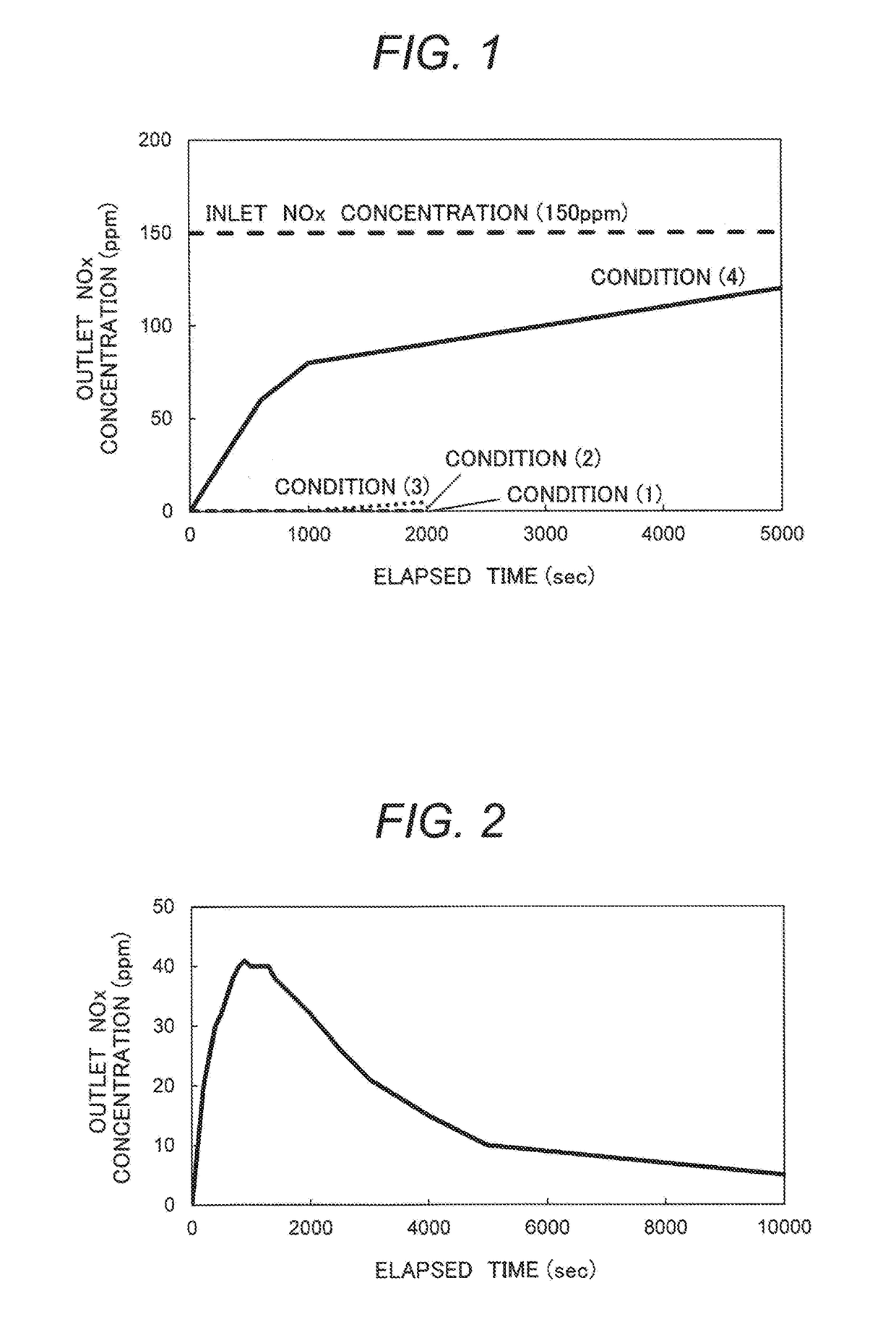
[0059]The CO2 scavenger was pelleted at 200 kgf by a press using a dye of 40 mm diameter, and then seized to a granular shape of 0.5 to 1.0 mm using a sieve after pulverization. Subsequently, 20.0 ml of granules were measured by using a measuring cylinder and they were fixed in a stainless steel tubular reactor. Impurities and gases adsorbed to the scavenger were removed by elevating a temperature to 200° C. and keeping for one hour using an electric furnace while flowing an N2 gas at 2.0 L / min. Subsequently, the temperature of the CO2 scavenger was cooled to 50° C. and the outlet NOx concentration was measured under four conditions of different compositions of flowin...

example 2

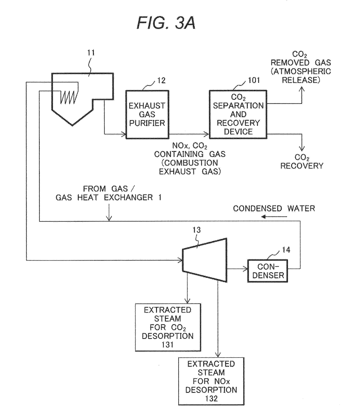
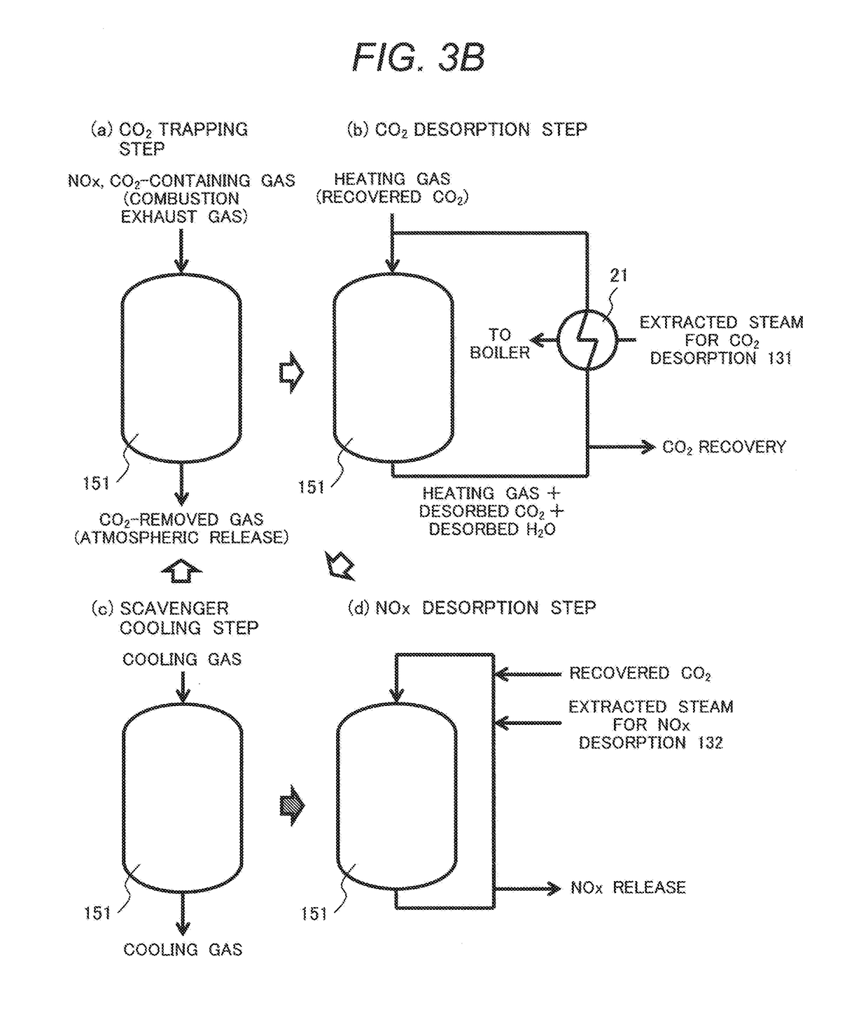
[0074]FIG. 3A illustrates a configuration of a device of separating and recovering CO2 from a combustion exhaust gas of a boiler in a thermal power generation station by utilizing characteristics of the CO2 scavenger shown in Example 1. Usually, the combustion exhaust gas contains nitrogen oxides and carbon dioxide. The combustion exhaust gas is also referred to as a gas to be processed.

[0075]The drawing shows, in addition to CO2 separation / recovery device 101, a boiler 11 of a thermal power generation station, an exhaust gas purifying device 12, a low pressure turbine 13, and a condenser 14. A trapping container of the CO2 separation / recovery device 101 contains a CO2 scavenger. They constitute a CO2 trapping unit.

[0076]The combustion exhaust gas discharged from the boiler 11 is subjected to processing such as denitration, desulfurization, dust removal, etc. in an exhaust gas purifying device 12, and then delivered to the CO2 separation / recovery device 101. In the CO2 separation / re...

example 3

[0091]FIG. 4 illustrates a configuration of suppressing NOx desorption in the CO2 desorption step in the CO2 separation / recovery device according to the present invention.

[0092]Other constitutions those that of the CO2 desorption step are identical with the constitutions illustrated in Example 2.

[0093]In this example, recovered CO2 is flowed as a heating gas to the trapping container 151. After flowing the gas discharged from the trapping container 151 (gas mixture of heating gas, desorbed CO2 and desorbed H2O) to the gas / gas heat exchanger 153, the gas is flowed to the condenser 157 to condensate and remove H2O. Subsequently, the gas discharged from the condenser 157 is flowed to the gas / gas heat exchanger 153, and the temperature is elevated by heat exchange. Subsequently, the gas is flowed to the gas / gas heat exchanger 155 and further subjected to heat exchange with extracted steam 131 from the steam turbine. In this case, the condenser 157 is an example of a dehumidifying part. ...


PUM

PropertyMeasurementUnit
Fractionaaaaaaaaaa
Fractionaaaaaaaaaa
Fractionaaaaaaaaaa

Abstract

A carbon dioxide separation/recovery device for separating and recovering carbon dioxide from a gas to be processed and containing nitrogen oxides and carbon dioxide by using a carbon dioxide scavenger, including a carbon dioxide trapping unit having the carbon dioxide scavenger, in which the carbon dioxide trapping unit includes: a gas flow inlet which introduces the gas to be processed; a heating unit of heating a scavenger heating gas used upon desorption of carbon dioxide trapped by the carbon dioxide scavenger to a predetermined temperature; a cooling gas introduction port which introduces a scavenger cooling gas used when cooling the carbon dioxide scavenger; and a moisture mixing part which adds moisture to a gas for nitrogen oxide desorption used in desorption of nitrogen oxides from the carbon dioxide scavenger. Consequently, NOx accumulated to the carbon dioxide scavenger is desorbed, thereby capable of suppressing lowering in the performance of the carbon dioxide scavenger and reducing the running cost.

Description

TECHNICAL FIELD[0001]The present invention relates to a carbon dioxide separation / recovery device, a combustion system using the same, a thermal power generation system using the same, and a method for separating and recovering carbon dioxide.BACKGROUND ART[0002]Global warming due to emission of greenhouse gases is a worldwide problem. The greenhouse gases include carbon dioxide (CO2), methane (CH4), chlorofluorocarbons (CFCs), etc. Among them, carbon dioxide gives a most significant effect and it is an urgent subject to constitute a system for separating and removing CO2 from thermal power generation plants, iron and steel manufacturing plants, etc.[0003]Further, CO2 gives undesired effects also on human bodies. For example, when a gas containing CO2 at a high concentration is inhaled, since this brings about health damages, CO2 concentration has to be controlled in a closed space, for example, inside a room. In particular, in a circumstance where ventilation between external air a...

Claims


Application Information

Patent Timeline
IPC IPC(8): B01D53/04B01D53/60B01D53/62B01D53/82B01J20/06
CPCB01D53/0438B01D53/60B01D53/62B01D53/82B01J20/06B01J20/3466F01K17/04B01D53/04B01J20/34B01D53/56Y02C20/40Y02A50/20Y02P20/151
Inventor YOSHIKAWA, KOHEIKANEEDA, MASATONAKAMURA, HIDEHIROAOSHIMA, MASAHIROSHIMAZAKI, TOSHIKATSU
Owner HITACHI CHEM CO LTD
Why Eureka
Try Eureka