Porous hollow fiber membrane, method for producing the same, and filtration method

a technology of porous fiber and hollow fiber, which is applied in the direction of membranes, membrane technology, chemistry apparatus and processes, etc., can solve the problems of practical use durability problems, and achieve the effects of good pore formability, high chemical resistance and mechanical strength

Inactive Publication Date: 2019-01-24
ASAHI KASEI KK
View PDF3 Cites 5 Cited by
  • Summary
  • Abstract
  • Description
  • Claims
  • Application Information

AI Technical Summary

Benefits of technology

[0066]According to the present disclosure, a porous hollow fiber membrane having a membrane structure forming a three-dimensional network structure, good pore formability, and high chemical resistance and mechanical strength is provided.

Problems solved by technology

With a certain type of crystalline resins, however, the membrane tends to have a spherocrystal structure, which has high strength but has low elongation and is brittle, and thus presents a durability problem in practical use.

Method used


Image

  • Porous hollow fiber membrane, method for producing the same, and filtration method

Examples


example 1

[0184]A melt-kneaded product was extruded using a spinning nozzle having a double tube structure to obtain a porous hollow fiber membrane of Example 1.

[0185]The melt-kneaded product was prepared using 40 mass % of PVDF resin (KF-W#1000, available from Kureha Corpolation) as the thermoplastic resin, 23 mass % of fine powder silica (primary particle size: 16 nm), and 32.9 mass % of bis(2-ethylhexyl) adipate (DOA, boiling point 335° C.) and 4.1 mass % of acetyl tributyl citrate (ATBC, boiling point 343° C.) as the solvent, The temperature of the melt-kneaded product was about 200° C. to 250° C.

[0186]The hollow fiber extrudate passed through a free running distance of 120 mm was then solidified in water at 30° C. to produce a porous hollow fiber membrane by the thermally induced phase separation process. The hollow fiber extrudate was taken up on a reel at a speed of 5 m / minute. The thus obtained double layer hollow fiber extrudate was immersed in isopropyl alcohol to extract and remove...

example 2

[0188]A porous hollow fiber membrane was produced in the same manner as in Example 1, except that the melt-kneaded product was prepared using 4.1 mass % of dibutyl sebacate (DBS, boiling point 345° C.) as the solvent in place of 4.1 mass % of acetyl tributyl citrate (ATBC, boiling point 343° C.).

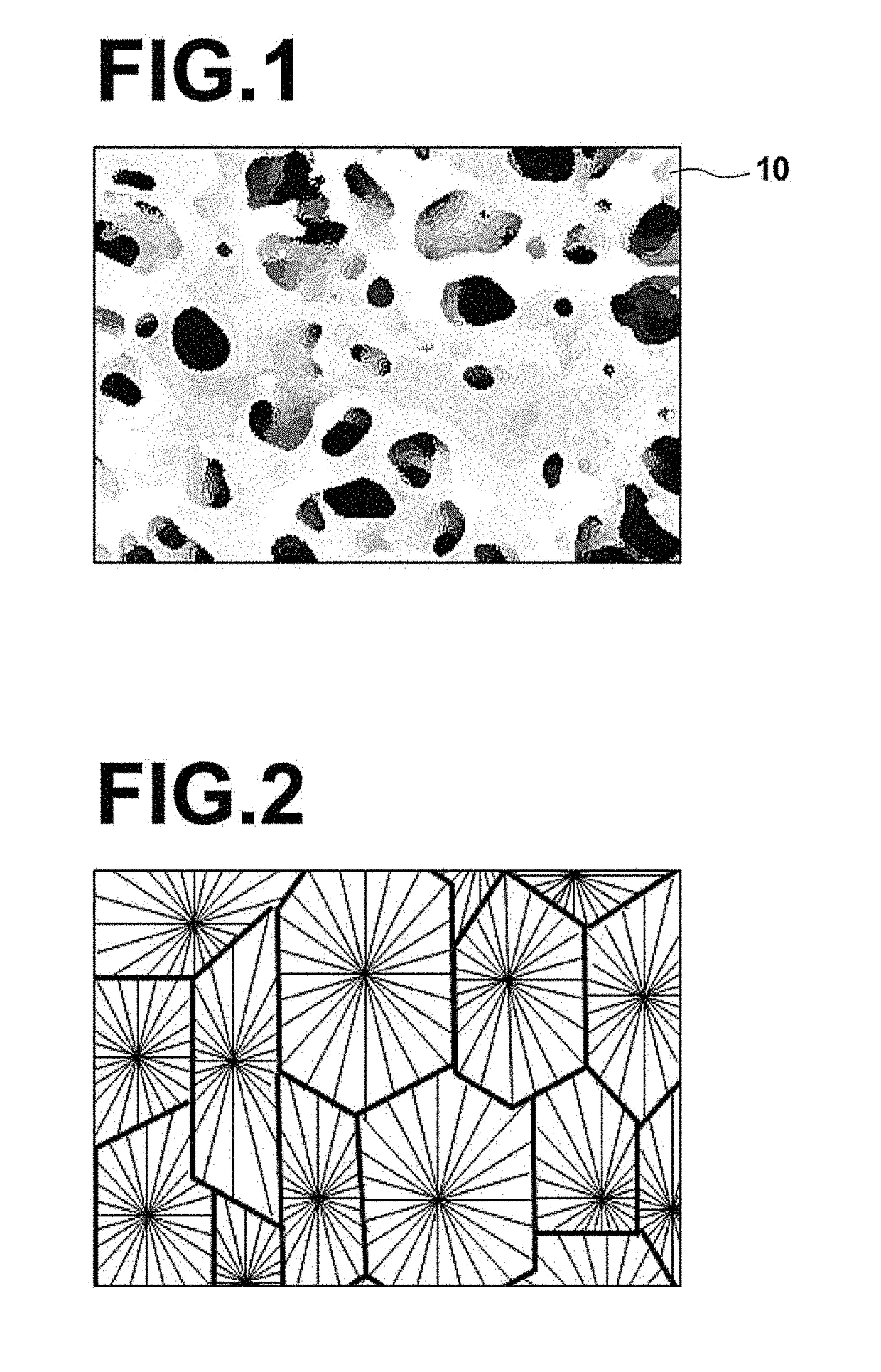
[0189]The formulation, production conditions, and various performances of the obtained porous hollow fiber membrane of Example 2 are shown in Table 1. The membrane structure of this porous hollow fiber membrane exhibited a three-dimensional network structure, such as one shown in FIG. 1.

example 3

[0190]A porous hollow fiber membrane was produced in the same manner as in Example 1, except that the melt-kneaded product was prepared using 32.9 mass % of diisononyl adipate (DINA, boiling point 250° C. or more) as the solvent in place of 32.9 mass % of bis(2-ethylhexyl) adipate (DOA, boiling point 335° C.).

[0191]The formulation, production conditions, and various performances of the obtained porous hollow fiber membrane of Example 3 are shown in Table 1. The membrane structure of this porous hollow fiber membrane exhibited a three-dimensional network structure, such as one shown in FIG. 1.


PUM

PropertyMeasurementUnit
tensile elongation at breakaaaaaaaaaa
temperatureaaaaaaaaaa

Abstract

A porous hollow fiber membrane includes at least a first solvent and a second solvent. The first solvent is at least one selected from sebacic acid esters, citric acid esters, acetyl citric acid esters, adipic acid esters, trimellitic acid esters, oleic acid esters, palmitic acid esters, stearic acid esters, phosphoric acid esters, C6-C30 fatty acids, and epoxidized vegetable oils. The second solvent is different from the first solvent, and is at least one selected from sebacic acid esters, citric acid esters, acetyl citric acid esters, adipic acid esters, trimellitic acid esters, oleic acid esters, palmitic acid esters, stearic acid esters, phosphoric acid esters, C6-C30 fatty acids, and epoxidized vegetable oils. The porous hollow fiber membrane has a three-dimensional network structure.

Description

TECHNICAL FIELD[0001]The present disclosure relates to a porous hollow fiber membrane, a method for producing the porous hollow fiber membrane, and a filtration method using the porous hollow fiber membrane.BACKGROUND ART[0002]Membrane filtration techniques using hollow fiber membranes to clarify liquid to be treated are being widely used in water treatment, sewage treatment, and the like. A thermally induced phase separation process is known as a method for producing hollow fiber membranes for use in the membrane filtration.[0003]In the thermally induced phase separation process, a thermoplastic resin and an organic liquid are used. In the thermally induced phase separation process using, as the organic liquid, a solvent that does not dissolve the thermoplastic resin at room temperature and dissolves the thermoplastic resin at high temperatures, i.e., a potential solvent (poor solvent), the thermoplastic resin and the organic liquid are kneaded at a high temperature to dissolve the...

Claims


Application Information

Patent Timeline
Patent Type & Authority Applications(United States)
IPC IPC(8): B01D71/34B01D69/08B01D69/02C08J9/26B01D67/00
CPCB01D71/34B01D69/08B01D69/02C08J9/26B01D67/0018C02F1/447B01D2325/24B01D2325/40B01D2325/30B01D2325/04B01D2325/02C02F1/44B01D69/087B01D71/32B01D2323/219
Inventor OKAMURA, DAISUKE
Owner ASAHI KASEI KK
Why Eureka
Try Eureka