Pyrolysis system and method of recovering carbon fibres from carbon-fibre-containing plastics

a carbon fibre and plastics technology, applied in the field of carbon fiber recovery (recycling) of carbon fibers from carbon fiber-containing plastics, can solve the problems of uneconomical disposal of cfp-containing plastic scrap in landfills, complicated and costly production of primary carbon fibers from carbon-containing starting materials, and high final product cost, so as to reduce the mechanical properties of recycled carbon fibers, reduce the effect of cfp-containing plastic scrap disposal and high quality

Active Publication Date: 2019-02-07
ELG CARBON FIBER INT
View PDF2 Cites 5 Cited by
  • Summary
  • Abstract
  • Description
  • Claims
  • Application Information

AI Technical Summary

Benefits of technology

[0054]In a conventional belt furnace of the prior art, the CFP material in the pyrolysis furnace is open toward the top and the pyrolysis gas formed can escape in an upward direction at any point, but there is insufficient circulation and mixing of the CFP material to be treated. When a conventional rotary tube in a rotary tube furnace of the prior art is used, the pyrolysis gas formed cannot, in contrast, escape in an upward direction, so that the pyrolysis gas would surround the CFP material and would hamper further pyrolysis. Although a conventional rotary tube furnace of the prior art would have some effect in respect of mixing and circulation of the CFP material, this would be countered by considerable disadvantages in respect of the lack of ability to discharge the pyrolysis gas formed during the pyrolysis. Only the use according to the invention or the provision according to the invention of the exit openings in the cylindrical wall on at least part of its length, namely at least where a particularly large amount of pyrolysis gas is formed, leads to an appropriate solution for a pyrolysis plant for recovering (recycling) carbon fiber-containing plastics.
[0055]The use of the pyrolysis plant of the invention, which comprises an indirectly heated rotary tube furnace having exit openings, firstly allows uniform mixing, circulation and heating of the CFP material in the pyrolysis furnace, and secondly efficient discharge of the pyrolysis gases through the exit openings in the rotary tube wall is at the same time made possible. This results in optimal pyrolysis conditions and thus in selective removal of only the polymer matrix without destruction of the carbon fibers to be recovered at any place in the rotary tube furnace, so that at least essentially no pyrolysis residues remain on the surface of the recycled carbon fibers after complete removal of the polymer matrix.
[0056]Furthermore, the exit openings in the indirectly heated rotary tube furnace of the pyrolysis plant of the invention allow control of the atmosphere, in particular the oxygen content, within the rotary tube furnace. In combination with the indirect heating of the rotary tube furnace, by means of which temperature fluctuations are avoided, a sel

Problems solved by technology

However, the use of carbon fiber-reinforced plastics (CFPs) leads, in comparison with the use of similar components composed of light metals such as aluminum, magnesium and titanium, to considerably higher costs of the final product.
This is related, in particular, to the complicated and costly production of primary carbon fibers from carbon-containing starting materials, in particular polyacrylonitrile (PAN).
In addition, large amounts of CFP-containing plastic scrap, which has to be disposed of, are obtained in the production of aircraft parts and parts for wind turbines and also as a result of modeling molds, production scrap, prototypes, incorrect batches and “end-of-life” components to be disposed of.
However, the disposal of CFP-containing plastics scrap in landfills is uneconomical because of the valuable carbon fibers present therein.
Furthermore, it can generally be expected that the CFP-containing plastics scrap remains unchanged over a long period of time because of its chemical inertness and cannot be degraded in landfills.
In addition, unlimited disposal of CFP-containing scrap is not readily possible or even prohibited because of legal requirements in many European countries.
Thus, it has hitherto been necessary to use sealed and complex pyrolysis plants and also complicated processes in order to ensure an inert atmosphere or the use of reduced pressure during the removal of the polymer matrix.
However, the pyrolysis is carried out over a long period of time, as a result of which the recycling is uneconomical and is not suitable for the industrial scale.
Furthermore, a complicated after-treatment of the recycled materials with further pyrolysis steps is provided in order to obtain carbon-containing shaped bodies.
Furthermore, circulation of the CFP material is not possible in the known pyrolysis plants using belt furnaces and the processes carried out therein for recovering carbon fibers from CFP material.
There is therefore no mixing of the CFP material and accordingly also no uniform heating of all regions of the CFP material present on the conveyor belt.
The result is considerabl

Method used


Image

  • Pyrolysis system and method of recovering carbon fibres from carbon-fibre-containing plastics
  • Pyrolysis system and method of recovering carbon fibres from carbon-fibre-containing plastics
  • Pyrolysis system and method of recovering carbon fibres from carbon-fibre-containing plastics

Examples


working examples

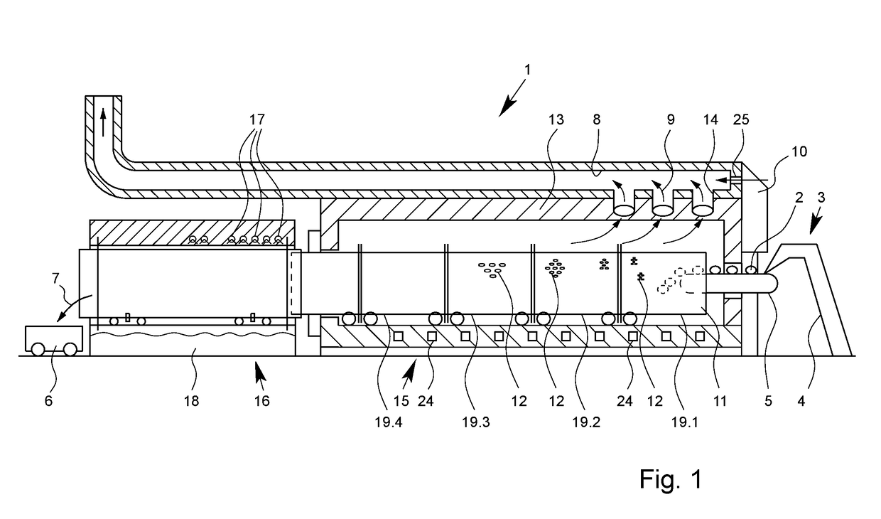
[0195]The particular advantages of the invention are described below for the example of the recovery (recycling) of carbon fibers from carbon fiber-containing materials.

A) Process for Recycling Carbon Fiber-Containing Plastics

[0196]Carbon fiber-reinforced plastic scrap (CFP scrap) as is obtained, for example, in aircraft construction (e.g. aircraft airfoils) or from wind power turbines (e.g. wind blades) is used as carbon fiber-containing plastics. If the pieces of CFP scrap have dimensions larger than the opening of the input station of the pyrolysis plant, comminution of the CFP scrap is carried out by means of cutting apparatuses which are known per se to those skilled in the art before recycling.[0197]The recycling of carbon fibers from the above-described carbon fiber-containing scrap in the form of prepregs is carried out in the pyrolysis plants indicated in table 1.

TABLE 1pyrolysis plants used for recyclingNo.pyrolysis plant1*pyrolysis plant having an indirectly heated rotary...


PUM

PropertyMeasurementUnit
Percent by volumeaaaaaaaaaa
Lengthaaaaaaaaaa

Abstract

The invention relates to a pyrolysis plant and a process for recovering (recycling) carbon fibers from carbon fiber-containing plastics, in particular from carbon fiber-reinforced plastics (CFPs or CFP materials), preferably from carbon fiber-containing and/or carbon fiber-reinforced composites (composite materials).

Description

CROSS-REFERENCES TO RELATED APPLICATIONS[0001]This patent application is a continuation of U.S. application Ser. No. 14 / 780,840, entitled “PYROLYSIS SYSTEM AND METHOD OF RECOVERING CARBON FIBRES FROM CARBON-FIBRE-CONTAINING PLASTICS” filed on Sep. 28, 2015, which claims priority to PCT / EP 2014 / 055980 filed on Mar. 25, 2014, to EP 13 001 625.6 filed Mar. 28, 2013, and to EP 13 001 994.6 filed Apr. 16, 2013, and incorporates all by reference herein, as if each one were independently incorporated in its entirety.BACKGROUND OF THE INVENTION[0002]The present invention relates to the technical field of recovery (recycling) of carbon fibers from carbon fiber-containing plastics, in particular from carbon fiber-reinforced plastics (CFPs), preferably from carbon fiber-containing or carbon fiber-reinforced composites (composite materials).[0003]In particular, the present invention relates to a pyrolysis plant for recovering (recycling) carbon fibers from carbon fiber-containing plastics, in p...

Claims


Application Information

Patent Timeline
IPC IPC(8): B29B17/02F27B7/20F23G5/033F23G5/027D01F9/14D01F9/12C10B53/07C10B47/30B09C1/06B29B17/04B29K105/06B29K707/04
CPCF23G5/033F27B7/20B29K2105/06B29B17/02B29B2017/0496D01F9/14C10B53/07D01F9/12B29K2707/04Y02P20/143Y02W30/622F23G5/0273Y02W30/625B09C1/065C10B47/30Y02W30/62B09C1/06
Inventor GEHR, MARCOWILCOX, LEESTREHLKE, INGO KURTALSOP, STEWART
Owner ELG CARBON FIBER INT
Why Eureka
Try Eureka