Conductive Polymer Dispersion for Improved Reliability

a technology of conductive polymer and reliability, applied in the manufacture of electrically-conductive capacitors, conductors, electrically-conductive paints, etc., can solve the problems of reliability problems, high dc leakage current, and difficulty in covering the edges and corners of dielectrics, and achieve better corner and edge coverage in capacitors.

Active Publication Date: 2019-04-18
KEMET ELECTRONICS CORP
View PDF2 Cites 2 Cited by
  • Summary
  • Abstract
  • Description
  • Claims
  • Application Information

AI Technical Summary

Benefits of technology

[0009]It is an object of the present invention to provide an improved conductive polymer capable of providing better corner and edge coverage in capacitor.

Problems solved by technology

One disadvantage is the difficulty associated with covering edges and corners of the dielectric.
Poor coverage of conducting polymers on corners and edges of anodized anodes results in high DC leakage current and causes reliability problems in humid atmosphere.
The resultant stress causes mechanical weakening of the interfaces.
In some cases this mechanical weakening causes delamination.
This interfacial weakness also results in higher ESR shift during high humidity environment.
However, the solid particles of conductive polymer does not contain polyanion which makes it non-disperive or insoluble in water.
Thus, the addition of solid particles of conducting polymer in conducting polymer:polyanion dispersion can affect dispersion stability, causes the dispersion to have a very high viscosity, settlements of solid particles in the dispersion, and results in poor reproducibility in performance.
No. 2015 / 0140203 A1, the solid particles makes the polymeric outer film brittle, which can cause the outer layer to flake off locally resulting in an increase in the residual current and in the ESR.
While crosslinkers are advantageous for improving the coating coverage on corners and edges of the anodized anode, the addition of these crosslinkers, which are mostly ionic in nature, has the unintended consequences of degrading the performance under humidity such as high ESR shift and increased DC leakage in a finished product.

Method used

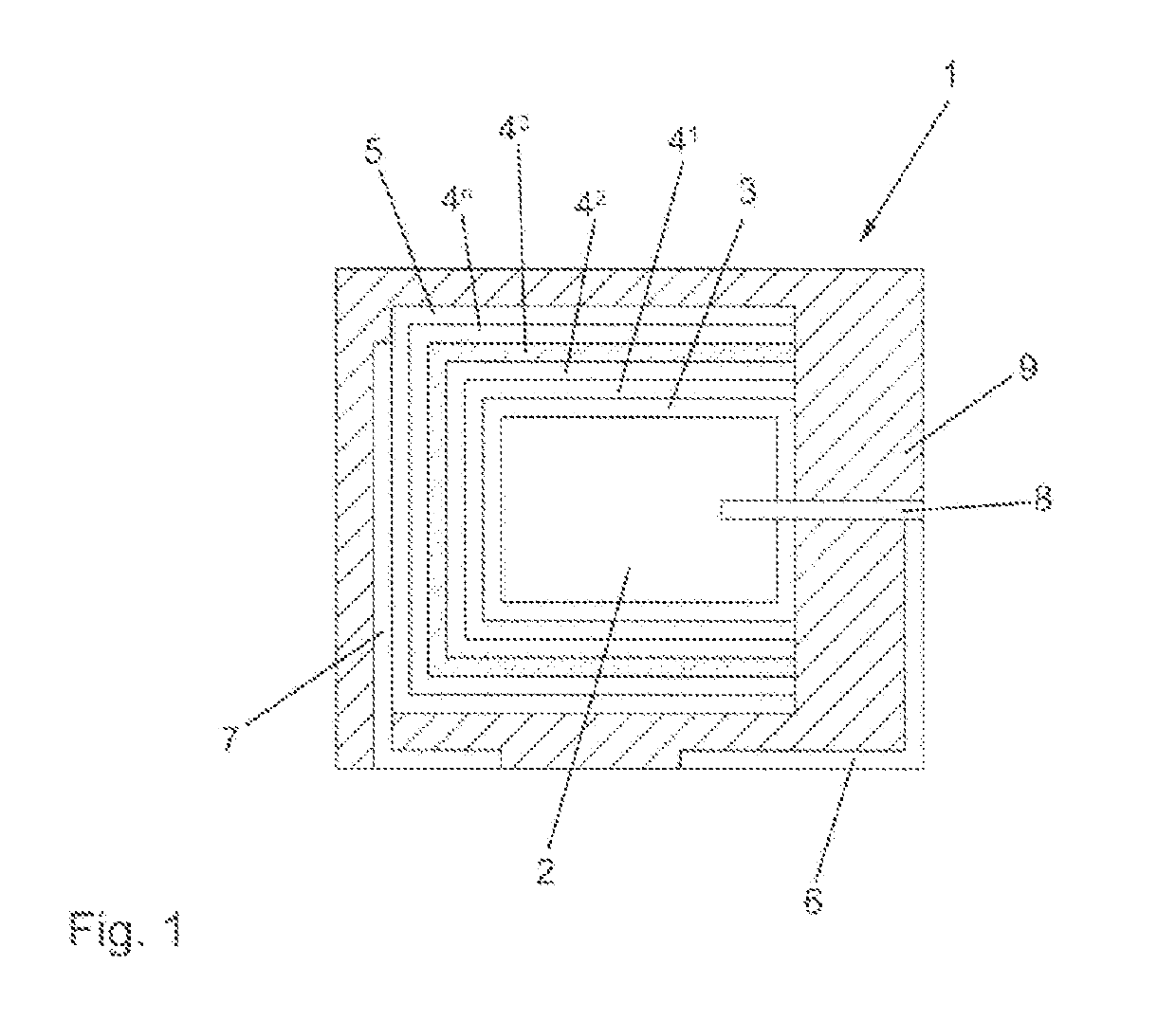
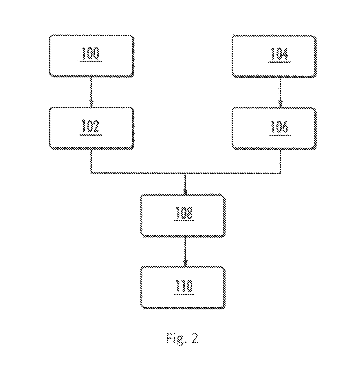

Image

  • Conductive Polymer Dispersion for Improved Reliability
  • Conductive Polymer Dispersion for Improved Reliability
  • Conductive Polymer Dispersion for Improved Reliability

Examples


example 1

[0088]Poly(4-styrenesulfonic acid-co-poly(ethylene glycol) methacrylate) sodium salt was synthesized. A 500 ml flask was initially charged with 33 ml deionized water as a solvent. After adding 8 g styrenesulfonic acid sodium salt, 2 g poly(ethylene glycol) methyl ether methacrylate (Mn 480) and 1 g ammonium persulfate, the mixture was saturated with nitrogen by means of a gas inlet tube. Nitrogen was passed through the mixture for 15 min. and during this time, the mixture was heated to 80° C. The flask was sealed with a rubber septum and the solution was allowed to polymerize for 16 hours. The resulting polyanion copolymer was acidified with dilute sulfuric acid and used directly for preparation of conducting polymer dispersion.

example 2

[0089]The conductive polymer dispersion was synthesized by high shear polymerization. 1740 g of DI water and 166 g of PSSA 30% (Alfa Aesar) were charged into a 4 L polyethylene bottle. The reaction solution was purged with nitrogen for 0.5-1 hr. The contents were mixed using a rotor-stator mixing system with perforated stator screen with a round hole diameter of 1.5 mm. Subsequently, 57 g of 1% ferric sulfate solution and 43 g of sodium persulfate were then added into the reaction mixture, followed by dropwise addition of 22.5 g of 3,4-ethylenedioxythiophene (EDOT) (Baytron M from Heraeus). The reaction mixture containing 3.56% solids of monomer and polyanion was sheared continuously with a shear speed at 4200 rpm for 24 hours. 600 g of Lewatit S108H and 600 g of Lewatit MP62WS ion exchange resins were added into the slurry and rolled at around 60 rpm overnight. The conductive polymer dispersion was separated from resins by filtration. The resulting poly(3,4-ethylenedioxythiophene) / ...

example 3

[0090]1740 g of DI water and 166 g of polyanion copolymer (30%) from Example 1 were charged into a 4 L polyethylene bottle. The reaction solution was purged with nitrogen for 0.5-1 hr. The contents were mixed using a rotor-stator mixing system with perforated stator screen with a round hole diameter of 1.5 mm. Subsequently, 57 g of 1% ferric sulfate solution and 43 g of sodium persulfate were then added into the reaction mixture, followed by dropwise addition of 22.5 g of 3,4-ethylenedioxythiophene (EDOT) (Baytron M from Heraeus). The reaction mixture containing 3.56% solids of monomer and polyanion was sheared continuously with a shear speed at 4200 rpm for 24 hours. 600 g of Lewatit S108H and 600 g of Lewatit MP62WS ion exchange resins were added into the slurry and rolled at around 60 rpm overnight. The conductive polymer dispersion was separated from resins by filtration. The resulting poly(3,4-ethylenedioxythiophene) / poly(4-styrenesulfonic acid-co-poly(ethylene glycol) methacry...


PUM

PropertyMeasurementUnit
wt %aaaaaaaaaa
wt %aaaaaaaaaa
particle diameteraaaaaaaaaa

Abstract

An improved capacitor is provided wherein the capacitor comprises a conductive polymer layer. The conductive polymer comprises first particles comprising conductive polymer and polyanion and second particles comprising the conductive polymer and said polyanion wherein the first particles have an average particle diameter of at least 1 micron to no more than 10 microns and the second particles have an average particle diameter of at least 1 nm to no more than 600 nm.

Description

BACKGROUND[0001]The present invention is related to improved solid electrolytic capacitors comprising conductive polymeric cathodes. More specifically, the present invention is related to improvements in the conductive polymer wherein the improved polymer composition provides improved coverage, particularly on edges and corners, thereby providing a capacitor with improved ESR and improved leakage stability in humid environments.[0002]Solid electrolytic capacitors are widely used throughout the electronics industry. In high voltage applications capacitors with a solid electrolyte, formed by conductive polymer dispersions, give excellent high voltage performance compared to conductive polymer cathodes formed in-situ. These conductive polymer dispersions are prepared by a number of process steps including polymerization, purification, filtration, homogenization, evaporation, etc. Descriptions of these processes are provided in U.S. Pat. Nos. 5,300,575; 7,990,684; 7,270,871; 6,000,840 a...

Claims


Application Information

Patent Timeline
Patent Type & Authority Applications(United States)
IPC IPC(8): H01G9/042C09D125/18C09D4/06C09D7/65C09D5/24C09D165/00
CPCC09D125/18C09D4/06C09D7/65C09D5/24H01G9/042C09D165/00C09D133/14C08G2261/3221C08G2261/3223C08G2261/794C08G2261/512H01G9/028H01B1/127H01G9/0036H01G9/0425H01G9/15C08F212/30C08L33/14C08L25/18C08F220/286H01G9/025C08F12/30
Inventor BUNHA, AJAYKUMARCHACKO, ANTONY P.CHEN, QINGPINGSHI, YARULESSNER, PHILIP M.
Owner KEMET ELECTRONICS CORP
Why Eureka
Try Eureka