Microfluidic Biochip With Enhanced Sensitivity

a micro-fluidic biochip and enhanced sensitivity technology, applied in fluid controllers, laboratory glassware, instruments, etc., can solve the problems of tedious and expensive disease diagnosis, and achieve the effects of increasing the sensitivity, enhancing the binding capability of antibodies, and increasing the quantity of cnts attached

Active Publication Date: 2019-04-25
NEW JERSEY INSTITUTE OF TECHNOLOGY
View PDF15 Cites 9 Cited by
  • Summary
  • Abstract
  • Description
  • Claims
  • Application Information

AI Technical Summary

Benefits of technology

[0019]Possible variations of the invention include, but are not limited to, the CNTs changed with different carboxylic groups and percentages of such groups so that the binding of antibodies can be increased. The density of the CNTs may also be altered to increase sensitivity.
[0020]Further inventive objects include but are not limited to the following. The invention contemplates attaching CNTs (carbon nanotubes) on the surface of the electrodes to enhanc...

Problems solved by technology

Disease diagnosis is still tedious a...

Method used


Image

  • Microfluidic Biochip With Enhanced Sensitivity
  • Microfluidic Biochip With Enhanced Sensitivity
  • Microfluidic Biochip With Enhanced Sensitivity

Examples


example i

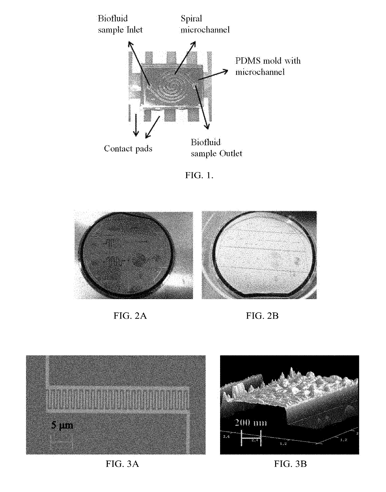
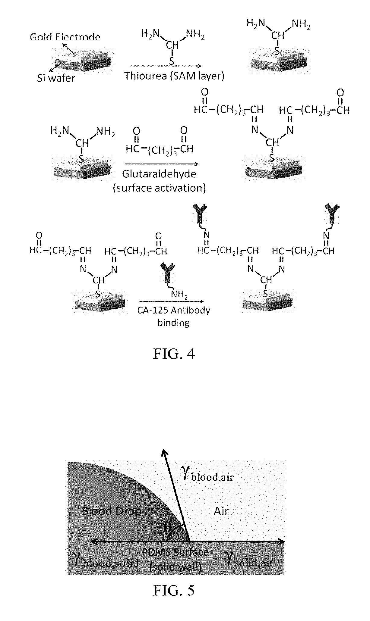
[0076]The primary steps involved in the fabrication of gold nano interdigitated electrodes were fabrication of gold nano interdigitated electrode (IDE) circuit and CA-125 Antibody immobilization on Electrodes. These steps are further described below. Again, these examples are given merely to explain the principles of the invention and are not meant to limit the scope of the invention to any particular embodiment.

[0077]For fabrication of the gold nano interdigitated electrode circuit (IDE) the silicon wafer was cut as per the dimensions desired and cleaned with isopropanol before starting the electrode fabrication. The Silicon wafer was then spin coated with positive tone photoresist. The photoresist used was PMMA-A6. The desired thickness of electrodes is 100 nm. The soft baking of the Silicon wafer was performed on a hot plate at around 180° C. for 120 seconds. The dimensions of the interdigitated electrodes fabricated were 500 nm width, 300 nm spacing (between the fingers) and 100...

example ii

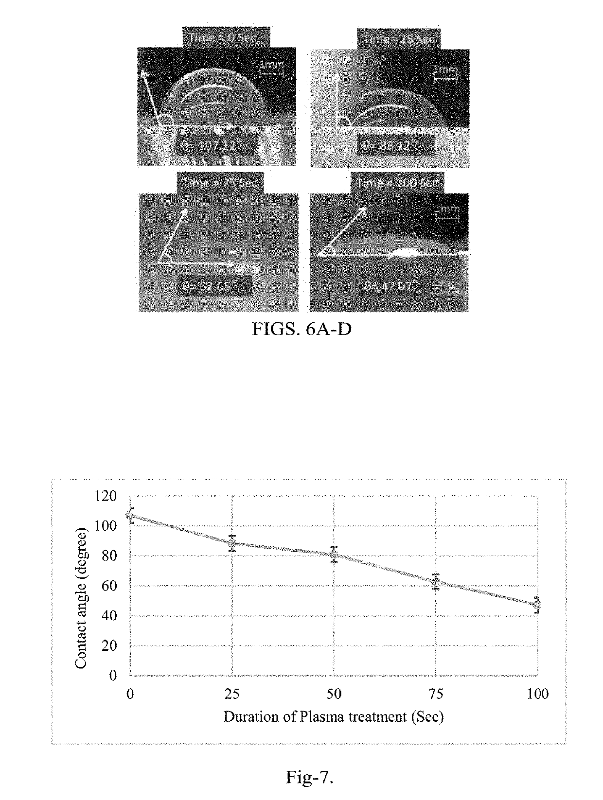
[0154]The detection and determination of the cancer biomarkers are very crucial to diagnose at the early stages of the disease. The biosensor of the present disclosure improves the detection by reducing the process time, cost and space of the device. A surface modification protocol is utilized for better sensitivity under shear flow rate conditions using carbon nanotubes (CNTs). An interdigitated electrode transducer was modified using functionalized CNTs for signal enhancement. The biosensor was integrated with PDMS microfluidic channels for controlled self-driven flow. Experimental results shown indicate disease-specific antigens, such as CA-125, are detected using the principles of the present disclosure from a micro volume of biofluid sample using the CNTs modified interdigitated electrodes under capillary flow condition. This result is a vast improvement over current state of the art biosensors.

[0155]In general, the invention overcomes the disadvantages of past attempts to dete...


PUM


Abstract

A microfluidic biochip for detecting disease antigens using gold nano interdigitated electrode circuit under a controlled self-driven flow condition is disclosed. The biochip incorporates hydrophilic microchannels for controlled self-driven flow and gold nano interdigitated electrodes for capacitive sensing with enhanced sensitivity. The biochip's microchannel has a surface treated with oxygen plasma to control microchannel surface hydrophilicity and flow rate of the biofluid sample. Carbon Nanotubes (CNTs) are utilized as an intermediate layer to enhance the binding capability to nano electrodes to enhance sensitivity. Due to the carboxylic groups of the CNTs, covalent bond binding between the antibodies and the CNTs allows the antibodies to adhere more readily on the surface of the electrodes. The quantity of antibodies attaching to the surface is increased due to the high surface to area ratio in CNTs.

Description

CROSS-REFERENCE TO RELATED APPLICATIONS[0001]The present application claims the benefit of the filing date of U.S. Provisional Patent Application No. 62 / 576,208 filed on Oct. 24, 2017, and U.S. Provisional Patent Application No. 62 / 589,097 filed on Nov. 21, 2017 the disclosures of which are hereby incorporated herein by reference.FIELD OF USE[0002]This disclosure relates to a micro biochip for detecting disease antigens by using interdigitated electrodes, and allows enhanced sensitivity in biosensing using the carbon nanotubes. More particularly, it relates to a novel way of detecting disease-specific antigens using gold nano interdigitated electrodes and carbon nanotubes in a controlled self-driven flow.BACKGROUND[0003]Early detection of a disease can improve patient treatment outcomes that help to save lives and also reduce patient treatment expenses significantly. Most diseases, such as cancer, are curable when they are detected in their early stages. For example, the survival ra...

Claims


Application Information

Patent Timeline
IPC IPC(8): B01L3/00C01B32/158G01N27/22G01N33/487G01N33/53G01N33/574
CPCG01N2800/7028B01L3/502715C01B32/158G01N27/226G01N33/48707G01N33/5304G01N33/57488B01L2300/0645B01L2300/0819B01L2300/0896B01L2300/12B01L2300/161B01L2400/0406B01L2400/08B82Y30/00B01L3/502746B01L3/502761B01L3/50273B01L2200/027B01L2300/023B01L2300/0883B01L2400/088B82Y15/00G01N33/5438G01N33/57449
Inventor LEE, EON SOONUNNA, BHARATH BABU
Owner NEW JERSEY INSTITUTE OF TECHNOLOGY
Why Eureka
Try Eureka