Micropatterning assembly, methods for micropatterning, and micropatterned devices

a technology of micropatterning and micropatterning components, applied in the field of micropatterning, can solve the problems of affecting the generation of homogenous gradients, affecting the quality of micropatterning, and affecting the quality of micropatterning, and achieve the effect of flexible and inexpensiv

Pending Publication Date: 2019-06-06
INST OF SCI & TECH AUSTRIA
View PDF1 Cites 0 Cited by
  • Summary
  • Abstract
  • Description
  • Claims
  • Application Information

AI Technical Summary

Benefits of technology

[0013]The present invention provides methods and devices for a block-based photopatterning approach which allows covalent or non-covalent immobilization of graded patterns of tagged molecules on background-free substrates in microscale resolution. The graded patterns include binary and / or grey values. The approach is flexible, inexpensive, independent of complex light sources and uses only basic tagging chemistry.

Problems solved by technology

One of the main challenges in such surface engineering is the independency of the reference substrate.
Especially passivating surfaces represent a challenge, since they have to offer high reactivity for patterning but also sustainable background passivation.
The arrays are based on self-assembled monolayers with either cell repellent or cell adhesive properties, thus it impedes the generation of homogenous gradients.
However, conventional LAPAP is applicable only for the immobilization of proteins and fails to achieve sufficiently high concentrations for demanding applications (e.g. immobilization of the RDG-peptide which requires a high density to be active in signaling) due to the linker size (e.g. linking antibody or streptavidin).
This can be inconvenient for applications which demand very high stability; the non-covalently immobilized molecules can e.g. be lost during stringent washing steps or heating.
However, exposure photobleaching can damage parts of the molecule which are intended to exert a biological or chemical function.
Moreover, the present micropatterning systems and methods imply some major disadvantages.
Conventional micropatterning assemblies are usually limited to produce binary patterns.
For instance, subtractive micropatterning methods such as photolithography, micro-contact-printing, UV-based chemistry and laser / electron beam etching (Strale et al., 2016, Piel and Théry, 2014) require powerful light sources, radical photochemistry and are limited to certain substrates.
When lasers are used as illumination source (e.g. LAPAP), laser safety requirements are to be followed, which makes said systems more complex, bulky and expensive.
Furthermore, there is no laser-related method available that ensures the fast generation of a high-resolution pattern.
The use of laser writing addresses only one location at a time which is inherently slow.

Method used


Image

  • Micropatterning assembly, methods for micropatterning, and micropatterned devices
  • Micropatterning assembly, methods for micropatterning, and micropatterned devices
  • Micropatterning assembly, methods for micropatterning, and micropatterned devices

Examples


example 1

ng

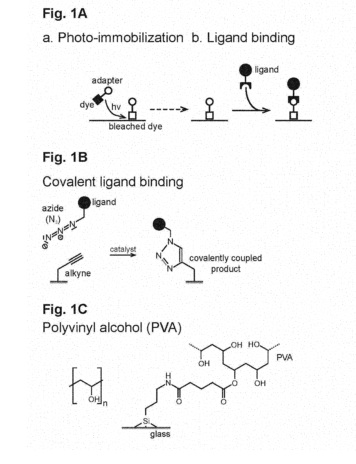
[0269]Glass bottom dishes (MaTek, USA) were polyvinyl alcohol (PVA) coated as described earlier (Doyle, 2001). Briefly, the glass surface of a MaTek dishes was activated for 25 min at room temperature with 50% nitric acid (Sigma Aldrich, St. Louis, Mo.). After activation, the dish was rinsed overnight in ddH2O. Subsequently, the glass surface was deprotonated by incubation for 15 min at room temperature with 200 mM NaOH (Sigma Aldrich, St. Louis, Mo.). The deprotonated and washed glass surface (ddH2O) was blow-dried using canned nitrogen. By incubation with 1% aqueous solution of APTES (w / v, Sigma Aldrich, St. Louis, Mo.), the glass surface was amino-silanized for 5 min and carefully washed with ddH2O for 10 min. The amino-silanized glass surface was then cured at 65° C. for 3 h. For aldehyde activation, surfaces were incubated with 0.5% aqueous glutaraldehyde (Sigma Aldrich, St. Louis, Mo.) solution for 30 min at room temperature. A ˜200 nm thick poly-vinyl alcohol (PVA, 6% aqueo...

example 2

obilization of FAM-Alkyne Laser Writing

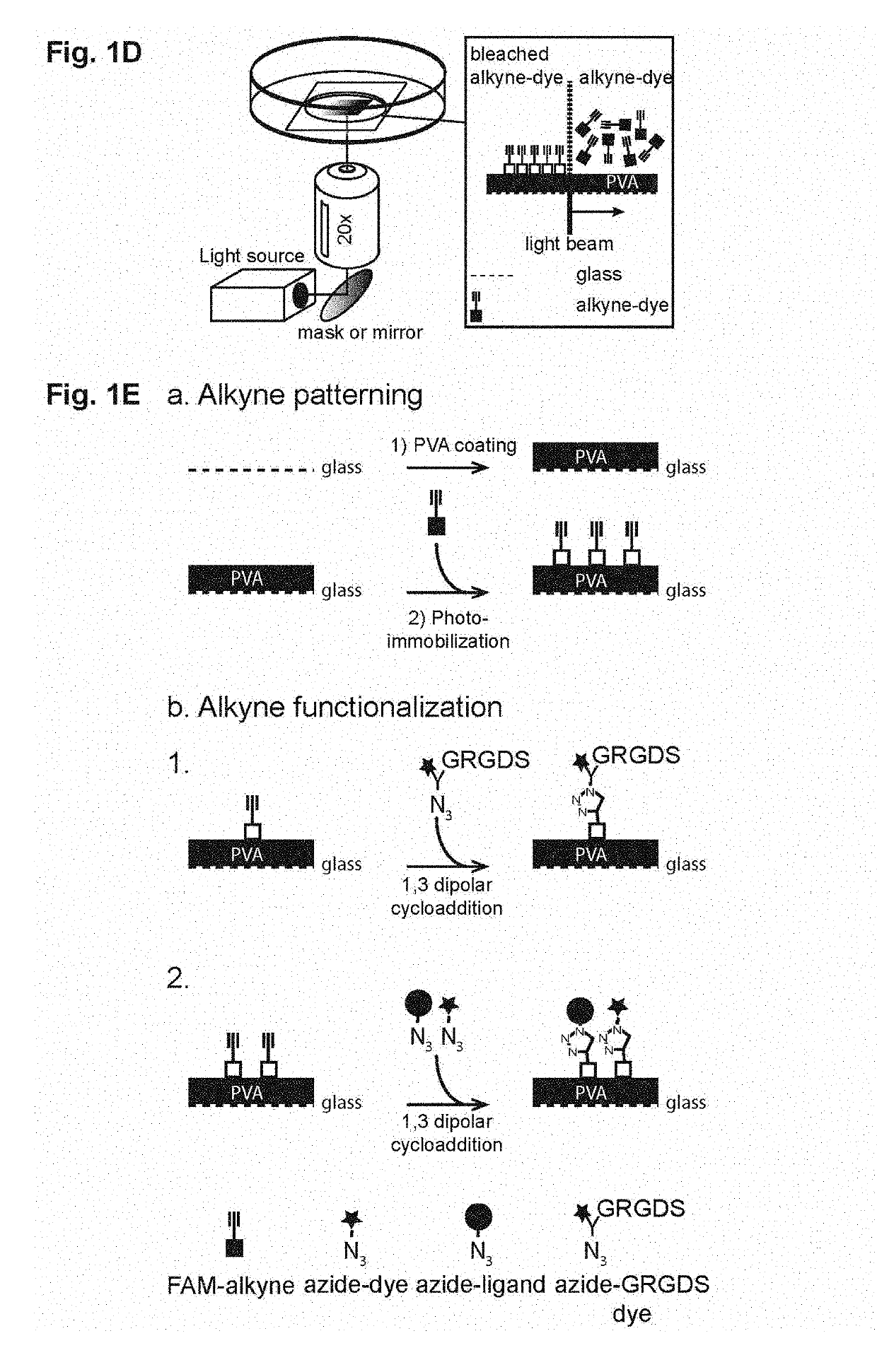
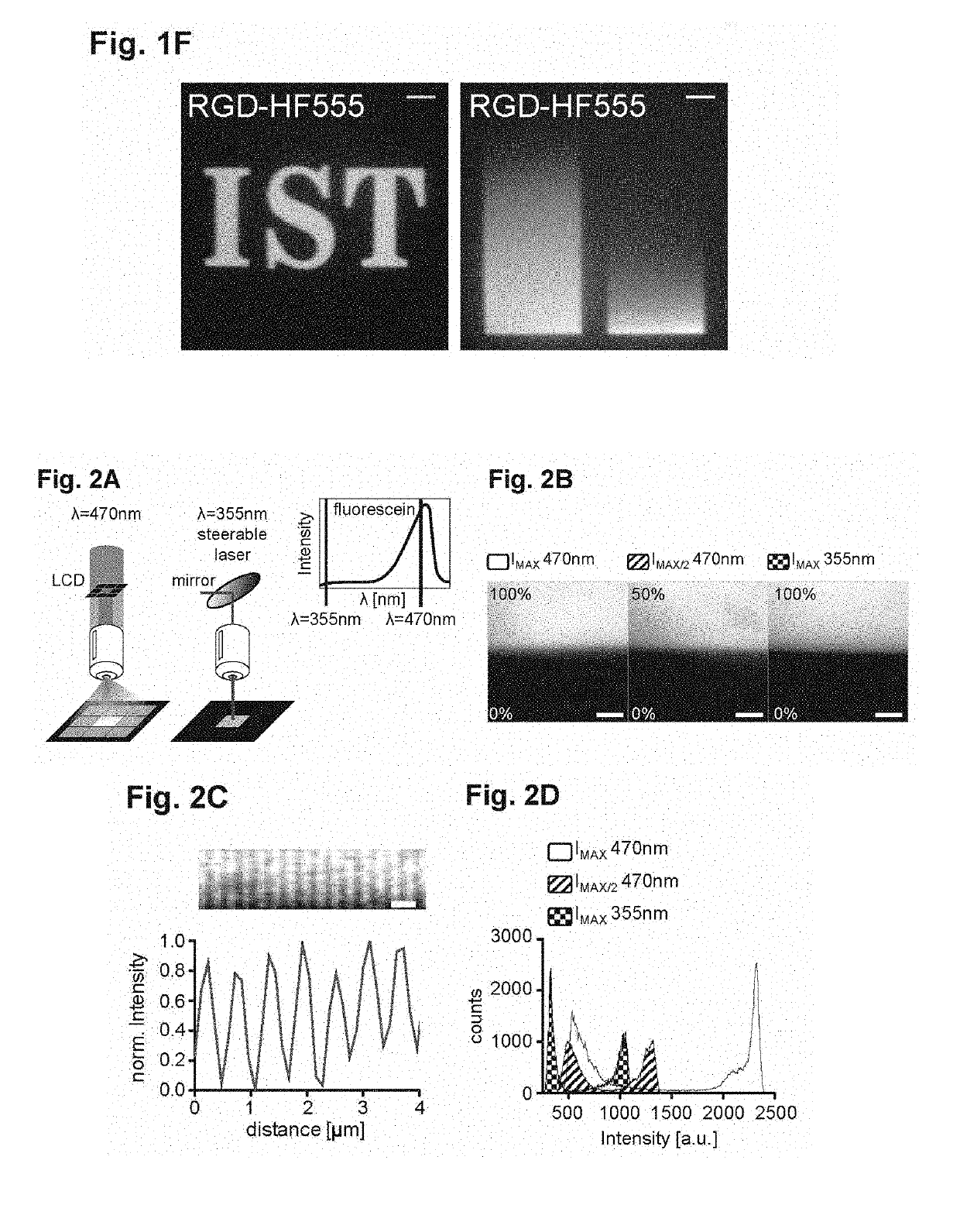
[0270]Approximately 20 μL FAM-alkyne (6-isomer, Lumiprobe, Hannover, Germany) were placed in the middle of a PVA coated glass dish and patterns were written using a steerable, pulsed UV laser (λ=355 nm) as described before (Weber et al., 2013). Briefly, the UV laser was focused into the interface between the bottom of the PVA coated glass slide and the FAM-alkyne solution with a long working distance 20× objective (Zeiss LD Plan Neo 20×0.4). A pair of high-speed galvanometric mirrors, controlled by a custom program, was moving the focal spot within the FAM-alkyne droplet.

[0271]The gradient pattern was specified by an image whose pixel values determined the light dose used for bleaching. Careful calibration allowed compensating for the off-center drop-off of numerical aperture of the objective as well as the geometric distortions from the imperfect imaging of the scan mirrors into the back aperture of the objective. This allowed gradient writing...

example 3-1 , 3

Example 3-1,3 Dipolar Cycloaddition

[0274]

TABLE 1Click reaction mixture.VolumeComponent2.2 μLClick-it cell reaction buffer (Thermo Fisher Scientific Inc.)19.8 μL ddH2O2.5 μLReaction buffer additive (Thermo Fisher Scientific Inc.)0.5 μLCuSO4  5 μLRGD-HF555 (30 μM)

[0275]GRGDS-HF555-Azide (RGD-HF555) was custom synthesized by Eurogentec (Serain, Belgium). Following laser writing or projector based patterning, the alkyne patterned PVA surfaces were washed with PBS and incubated for 30 min in the dark with the reaction mixture (Table 1). After washing with PBS, RGD-HF555 patterns can be stored for up to a month under PBS.


PUM

PropertyMeasurementUnit
wavelengthaaaaaaaaaa

Abstract

The present invention relates to the field of micropatterning. In particular, the present invention provides micropatterning assemblies and methods for micropatterning. Moreover, the present invention provides micropatterned devices obtained by using the micropatterning assemblies and/or methods of the invention. Furthermore, the present invention provides methods for using said devices.

Description

FIELD OF THE INVENTION[0001]The present invention relates to the field of micropatterning. In particular, the present invention relates to micropatterning assemblies and methods for micropatterning. Moreover, the present invention relates to micropatterned devices obtained by using the micropatterning assemblies and / or methods of the invention, as well as to methods for using said devices.Background[0002]In the recent years micropatterning became an essential tool in biomaterials engineering and cellular biology. Micropatterning is the spatially and quantitatively controllable deposition of molecules on surfaces. Micropatterning of extracellular signaling or adhesion molecules on cell culture surfaces became an essential tool in all experimental fields operating with cultured cells (Ricoult et al., 2015; Théry, 2010). For example, micropatterns have been used to control the geometry of adhesion and substrate rigidity. Further, in order to study the influence of cellular environment ...

Claims


Application Information

Patent Timeline
Patent Type & Authority Applications(United States)
IPC IPC(8): G01N33/543C12M1/00C12N5/00G01N33/569
CPCG01N33/54353C12M23/20C12N5/0068G01N33/54393G01N33/569C12N2535/10
Inventor SIXT, MICHAELHAUSCHILD, ROBERTSCHWARZ, ALEXANDER JANNEMETHOVA, MARIA
Owner INST OF SCI & TECH AUSTRIA
Why Eureka
Try Eureka