Filter medium, method for manufacturing same, and filter module comprising same

Active Publication Date: 2019-06-13
AMOGREENTECH CO LTD
View PDF7 Cites 6 Cited by
  • Summary
  • Abstract
  • Description
  • Claims
  • Application Information

AI Technical Summary

Benefits of technology

[0037]According to the present invention, flux can be considerably increased due to improved hydrophilicity of a filter medium. Hydrophilicity can be maintained for a long period of time and thus a use cycle can be considerably increased.

Problems solved by technology

However, since a diameter of a short fiber included in a general nonwoven fabric is in the unit of microns, there is a limitation in implementing a separation membrane having a fine and uniform pore structure only by controlling a diameter and basis weight of a fiber.
Accordingly, only a separation membrane such as a microfiltration membrane may be implemented using a general nonwoven fabric, and it is difficult to implement a separation medium such as an ultrafiltration membrane or a nanofiltration membrane for filtering finer particles.
However, it is difficult to prepare a microfiber having a nanoscale diameter by spinning only once through a general fiber pinning process such as a wet spinning process, and it is necessary to spin sea-island yarn or the like and separately elute a sea component to obtain an island component wh

Method used

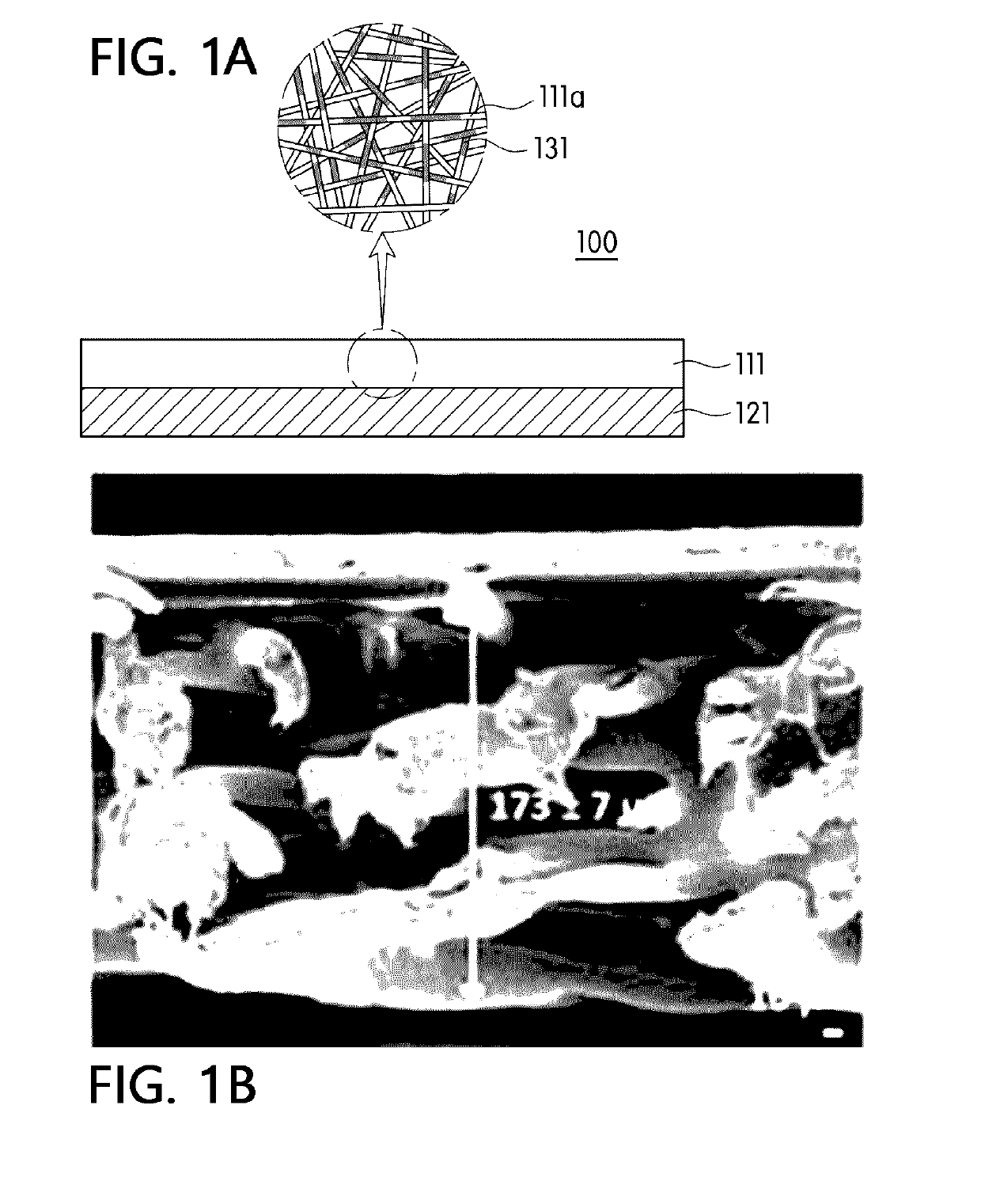

Image

  • Filter medium, method for manufacturing same, and filter module comprising same
  • Filter medium, method for manufacturing same, and filter module comprising same
  • Filter medium, method for manufacturing same, and filter module comprising same

Examples


Example

Example 1

[0088]First, in order to prepare a spinning solution, 12 g of PVDF (Kynar 761 manufactured by Arkema Inc.) as a fiber-forming component was dissolved in 88 g of a mixed solution, which is obtained by mixing dimethylacetamide and acetone in a weight ratio of 70:30, at a temperature of 80° C. for 6 hours using a magnetic bar to prepare a mixed solution. The spinning solution was introduced into a solution tank of an electrospinning device and was ejected at a rate of 15 μl / min / hole. Here, temperature of a spinning section was maintained at 30° C., humidity was maintained at 50%, and a distance between a collector and a tip of a spin nozzle was 20 cm. After that, a voltage of 40 kV or more was applied to a spin nozzle pack using a high voltage generator, and concurrently, an air pressure of 0.03 MPa was applied to each nozzle of the spin pack to form a fiber web layer composed of a PVDF nanofiber. Next, in order to dry a solvent and moisture remaining in the fiber web layer, a...

Example

Examples 2 to 18

[0091]A filter medium like that shown in Table 1, 2, or 3 below was manufactured in the same manner as in Example 1, except that a composition and the like of a hydrophilic coating composition was changed as in Table 1, 2, or 3 below.

Example

Comparative Example 1

[0092]A filter medium like that shown in Table 3 below was manufactured in the same manner as in Example 1, except that there was no treatment with a hydrophilic coating composition.


PUM

PropertyMeasurementUnit
Fractionaaaaaaaaaa
Fractionaaaaaaaaaa
Fractionaaaaaaaaaa

Abstract

A filter medium is provided. A filter medium according to an embodiment of the present invention comprises: a fiber web layer of a three-dimensional network structure including nanofiber; and a hydrophilic coating layer which covers at least a part of the outer surface of the nanofiber. According to this, a flow rate can be remarkably increased due to the improved hydrophilicity of the filter medium. Also, as the improved hydrophilicity is maintained for a long period of time, the lifespan can be remarkably prolonged. Furthermore, since the modification of a porous structure of the filter medium is minimized during the process of hydrophilization so that the initially designed physical properties of the filter medium can be exhibited in its entirety, the filter medium having chemical resistance, excellent water permeability and durability can be variously applied in the water treatment field.

Description

CROSS REFERENCE TO RELATED APPLICATION[0001]This application is a 35 U.S.C. 371 National Phase Entry Application from PCT / KR2017 / 005735, filed Jun. 1, 2017, which claims the benefit of Korean Patent Application No. 10-2016-0069040 filed on Jun. 2, 2016, the disclosures of which are incorporated herein in their entirety by reference.TECHNICAL FIELD[0002]The present invention relates to a filter medium, and more specifically, to a filter medium which has high water permeability as well as high durability, a method of manufacturing the filter medium, and a filter module including the filter medium.BACKGROUND ART[0003]Separation membranes may be classified into microfiltration (MF) membranes, ultrafiltration (UF) membranes, nanofiltration (NF) membranes, and reverse osmosis (RO) membranes according to a pore size.[0004]Although the above-exemplified separation membranes differ in usages and pore sizes, the separation membranes have a common feature of being filtration media composed of ...

Claims


Application Information

Patent Timeline
IPC IPC(8): B01D69/02B01D63/08B01D69/10B01D71/34B01D71/38B01D67/00D01F6/12D06M15/333D01D5/00D04H1/4318D04H1/558D04H1/728D01F8/06
CPCB01D69/02B01D63/08B01D69/10B01D71/34B01D71/38B01D67/0002B01D67/0088D01F6/12D06M15/333D01D5/003D01D5/0084D04H1/4318D04H1/558D04H1/728D01F8/06B01D2325/02B01D2325/36B01D2323/39D10B2505/04D06M2101/26D10B2401/022D10B2401/021D10B2321/022D10B2321/021B01D71/32B01D63/067B01D2323/02B01D2323/30D04H1/587D04H1/64B01D39/1623B01D2239/025B01D2239/0421B01D2239/1208B01D2239/1233B01D2239/065B01D2239/0654D01D5/0038D06M2101/22B01D2321/281D04H1/54B01D2239/0471D01F8/00
Inventor JEONG, UI YOUNGSEO, IN YONG
Owner AMOGREENTECH CO LTD
Why Eureka
Try Eureka