Broadcast Relaying via Cooperative Multi-Channel Transmission

a multi-channel transmission and broadcast relay technology, applied in the field of communication systems, to achieve the effect of cost saving

Active Publication Date: 2019-06-27
SINCLAIR BROADCAST GRP
View PDF17 Cites 17 Cited by
  • Summary
  • Abstract
  • Description
  • Claims
  • Application Information

AI Technical Summary

Benefits of technology

[0007]The present invention describes a new hybrid broadcast SFN system architecture that does not require a Studio-to-Transmitter Link (STL) to send content (data) preprocessed from a central master SFN Gateway node along with timing and metadata directly to every exciter node at each SFN transmitter site. The difference in a relay mode architecture is that the exciter node receives content (data), SFN timing, and / or metadata via an over the air (OTA) RF relay link from another SFN transmitter node directly connected to central Gateway by STL (e.g., fiber, microwave, or the like). The content (data) received from relay is then processed using timing and signaling to create an RF waveform which becomes a coherent broadcast signal from the transmitter site in SFN. Therefore, a harmonized hybrid SFN system architecture is possible using a combination of both traditional STL and OTA RF relays to SFN exciter nodes at transmitter sites using the methods in this disclosure. The SFN relay mode can be technically enabled using some multiplexing technique supported in ATSC 3.0. Time Division Multiplexing (TDM) and Layer Division Multiplexing (LDM) will be described, compared and benefits discussed along with potential use cases. The result of using SFN relay mode is more degrees of freedom for network operator to engineer and locate SFN transmitter sites where they may have the most benefit without constraint of bringing fiber, microwave to each site. There can be an unlimited number of SFN relay transmitter sites with a wide range of effective radiated power (from milliwatts to kilowatts, depending on the implementation) that can be used to improve Quality of Service (QoS) by placing a broadcast signal (SFN) where it is needed to fill in service gaps, serve both indoor and outdoor locations, create hotspots in urban areas and at venues (e.g., stadiums, arenas, or the like) and / or by mounting on existing cellular towers which helps enable new wireless broadcast business models and new services for consumers. Therefore, the SFN relay nodes can result in increased spectrum efficiency and improvement in QoS. This service can be provided by a third party for any combination of broadcasters in a market, much like a Distributed Antenna System (DAS) in 3GPP LTE-A cellular is deployed for mobile network operators (MNO) in market today.
[0009]A Next Gen Broadcast Platform (NGBP) represents a new broadcast system architecture and paradigm shift that enables broadcast licensees to come together using shared licensed broadcast spectrum resources and a common infrastructure to create a multi-tenant virtualized broadcast cloud model instead of operating traditionally as independent isolated islands. This sharing of spectrum resource and infrastructure can enable cost savings but moreover innovation to remain competitive in a free wireless market.

Problems solved by technology

The challenge is finding a method to provide all transmitters with the same content (data) and necessary signaling, timing information to broadcast on the same frequency without becoming interferers to one another but to improve the received quality of service.

Method used


Image

  • Broadcast Relaying via Cooperative Multi-Channel Transmission
  • Broadcast Relaying via Cooperative Multi-Channel Transmission
  • Broadcast Relaying via Cooperative Multi-Channel Transmission

Examples


Embodiment Construction

[0038]It should be appreciated that the following acronyms and abbreviations may be used herein:

[0039]ATSC Advanced Television Systems Committee

[0040]AWGN Additive White Gaussian Noise

[0041]BICM Bit-Interleaved Coded Modulation

[0042]dB Decibels

[0043]FEC Forward Error Correction

[0044]FFT Fast Fourier Transform

[0045]GI Guard Interval

[0046]GPS Global Positioning System

[0047]LDM Layer Division Multiplexing

[0048]LDPC Low Density Parity Check

[0049]MHz MegaHertz

[0050]NFV Network Function Virtualization

[0051]OFDM Orthogonal Frequency Division Multiplexing

[0052]OTA Over-the-Air

[0053]PLP Physical Layer Pipe

[0054]QAM Quadrature Amplitude Modulation

[0055]QPSK Quadrature Phase Shift Keying

[0056]RF Radio Frequency

[0057]SDN Software-Defined Networking

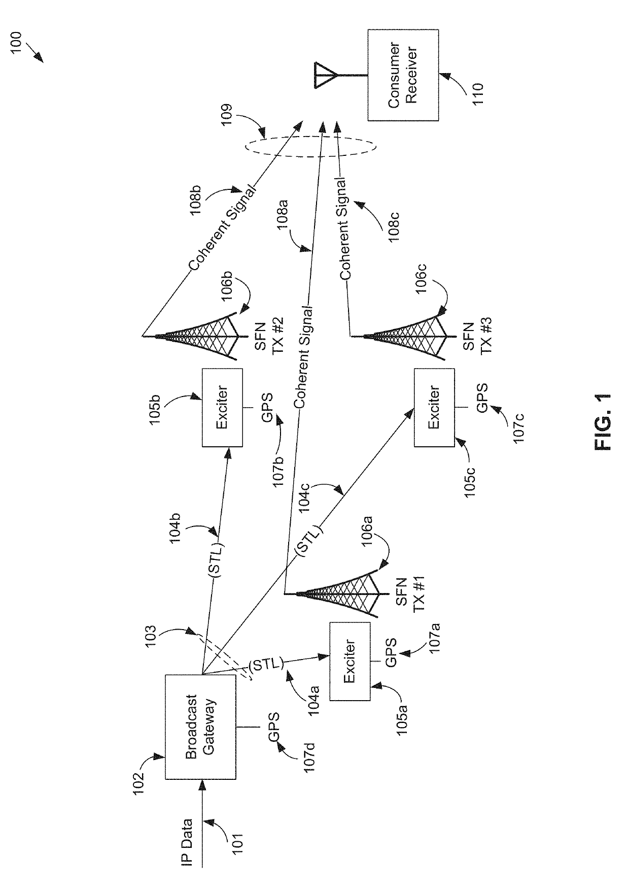
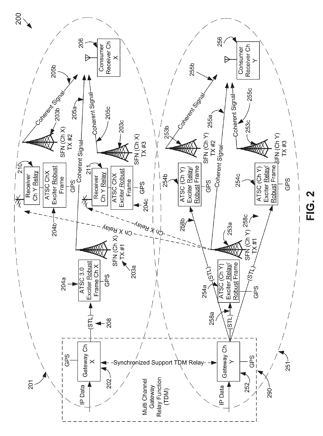
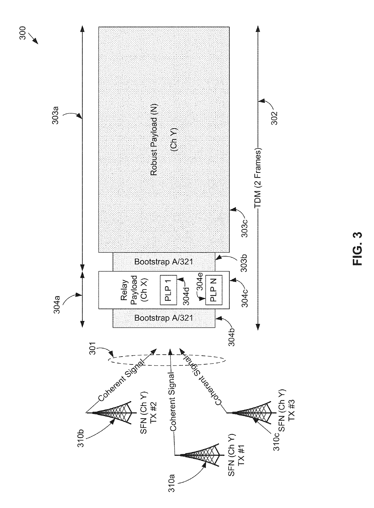
[0058]SFN Single Frequency Network

[0059]SNR Signal-to-Noise Ratio

[0060]STL Studio-to-Transmitter Link

[0061]International Atomic Time

[0062]TDM Time Division Multiplexing

[0063]TX Transmitter

[0064]VNF Virtual Network Function

[0065]Broadcast Single-Freque...


PUM


Abstract

Systems and methods for relaying in broadcast single-frequency networks are disclosed herein. A single-frequency network can be formed in part using transmitters that receive data via a cooperative relay channel instead of a station-to-transmitter link. In some embodiments, a second channel may use a portion of its transmission time to relay the information to the single-frequency network transmitter using time-division multiplexing. In other embodiments, a second channel may encode the relayed information on a second layer using layer-division multiplexing.

Description

CROSS-REFERENCE TO RELATED APPLICATIONS[0001]The present application claims the benefit of U.S. Provisional Patent Application No. 62 / 586,055, filed on Nov. 14, 2017, which is hereby incorporated by reference in its entirety.BACKGROUNDField[0002]The present disclosure relates to communications systems, including multi-channel single-frequency network broadcast systems.Related Art[0003]The notion of a broadcast single frequency network (SFN) has been used in terrestrial broadcasting to increase the spectrum efficiency and improve the service quality of a broadcast service. This can be done by using some technique of enabling the same content (data) to be broadcast from multiple transmitters all operating on the same frequency and to produce identical radio frequency (RF) waveforms (coherent signals) exactly at the same instant in time. The challenge is finding a method to provide all transmitters with the same content (data) and necessary signaling, timing information to broadcast on...

Claims


Application Information

Patent Timeline
Patent Type & Authority Applications(United States)
IPC IPC(8): H04H20/33H04L1/00
CPCH04H20/33H04L1/0071H04L1/0076H04L1/0057H04B7/0413H04B7/15592H04H20/02H04H20/18H04H20/67H04N7/08H04N21/234327H04N21/2385H04N21/6112H04N21/631H04J11/004H04N21/2358
Inventor SIMON, MICHAEL JOHNLIBIN, LOUIS HERBERT
Owner SINCLAIR BROADCAST GRP
Why Eureka
Try Eureka