Enhanced performance hybrid three-level inverter/rectifier

Active Publication Date: 2019-08-01
GAN SYST
View PDF0 Cites 21 Cited by
  • Summary
  • Abstract
  • Description
  • Claims
  • Application Information

AI Technical Summary

Benefits of technology

[0030]Devices and systems comprising a 3-level NPC inverter/rectifier or a 3-level T-Type NPC inverter/rectifier, and methods of their operation, are disclosed that s

Problems solved by technology

SiC MOSFETS and diodes offer performance advantages for the t

Method used


Image

  • Enhanced performance hybrid three-level inverter/rectifier
  • Enhanced performance hybrid three-level inverter/rectifier
  • Enhanced performance hybrid three-level inverter/rectifier

Examples


Embodiment Construction

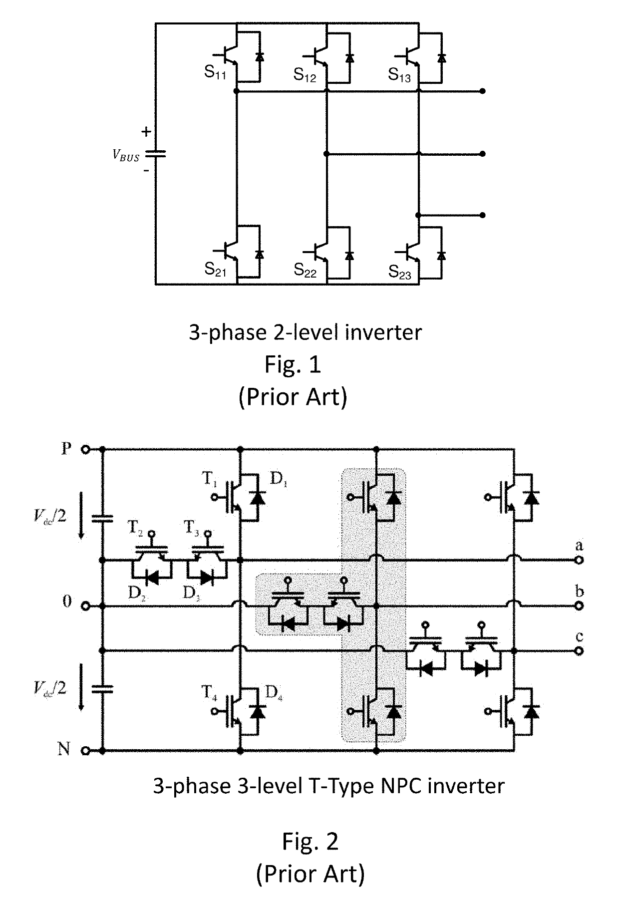
[0048]A circuit schematic for a three phase 2-level inverter topology comprising Si IGBTs and Si anti-parallel diodes is shown in FIG. 1 (Prior Art). Each phase leg comprises a high side power switch S1 and a low side power switch S2. Each switch comprises a Si IGBT and an anti-parallel diode, which may be referred to as a free-wheeling diode (FWD). The anti-parallel diode may be a low-cost silicon diode, or a SiC Schottky barrier diode (SBD). Each switch must be capable of blocking the entire input voltage Vdc. For example, for an EV or HEV traction inverter of e.g. 50 kW to 80 kW, the operating voltage supplied from a battery bank may have a DC link voltage in the range of 750V to 900V. Thus, for this power application, 1200V Si IGBTs would typically be used for each power switch S1 and S2.

[0049]A circuit schematic for a three-phase T-type Neutral Point Clamped (NPC) 3-level inverter topology comprising Si IGBTs and anti-parallel diodes is shown in FIG. 2 (Prior Art). As for the 2...


PUM


Abstract

A 3-level T-type neutral point clamped (NPC) inverter/rectifier is disclosed in which neutral point clamping is dynamically enabled/disabled responsive to load, e.g. enabled at low load for operation in a first mode as a 3-level inverter/rectifier and disabled at high/peak load for operation in a second mode as a 2-level inverter/rectifier. When the neutral clamping leg is enabled only under low load and low current, middle switches S2 and S3 can be smaller, lower cost devices with a lower current rating. Si, SiC, GaN and hybrid implementations provide options to optimize efficiency for specific load ratios and applications. For reduced switching losses and enhanced performance of inverters based on Si-IGBT power switches, a hybrid implementation of the dual-mode T-type NPC inverter is proposed, wherein switches S1 and S4 comprise Si-IGBTs and switches S2 and S3 of the neutral clamping leg comprise GaN HEMTs. Applications include electric vehicle traction inverters.

Description

CROSS-REFERENCE TO RELATED APPLICATION(S)[0001]This application claims priority from U.S. provisional patent application No. 62 / 624,285 entitled “Enhanced Performance Hybrid Three-Level Inverter / Rectifier” filed Jan. 31, 2018, which is incorporated herein by reference in its entirety.TECHNICAL FIELD[0002]This invention relates to three-level Neutral Point Clamped (NPC) inverters / rectifiers, with particular application to performance enhancement of inverters / rectifiers for power applications, such as electric vehicle traction inverters.BACKGROUND[0003]A two-level inverter topology, as illustrated in FIG. 1, is commonly implemented using either all silicon (Si) technology or all silicon carbide (SiC) technology. That is, the switching transistors are implemented in Si technology using Si IGBTs (Insulated Gate Bipolar Transistors) with Si anti-parallel diodes. Alternatively, the switching transistors are SiC MOSFETS (Metal Oxide Semiconductor Field Effect Transistors) and the anti-para...

Claims


Application Information

Patent Timeline
IPC IPC(8): H02M7/487H02M7/537H03K17/0412H03K17/12H03K17/284H03K17/60H03K17/687H01L29/739
CPCH02M7/487H02M7/537H03K17/04123H03K17/122H03K17/284H03K17/602H03K17/6872H01L29/7393H01L29/1608H01L29/2003H02M1/0054
Inventor LU, JUNCHENGCHEN, DISPAZIANI, LARRY
Owner GAN SYST
Why Eureka
Try Eureka