Method for producing photoluminescent particles
a technology of photoluminescent nanoparticles and manufacturing methods, which is applied in the direction of luminescent compositions, photomechanical devices, climate sustainability, etc., can solve the problems of low crystallinity, external quantum efficiency of particles, and decrease of photoluminescent performance of photoluminescent nanoparticles
- Summary
- Abstract
- Description
- Claims
- Application Information
AI Technical Summary
Benefits of technology
Problems solved by technology
Method used
Image

Examples
example 4
[0140]The YAG:Ce3+ microparticle powder of example 1 has been used to form a nanoparticle powder.
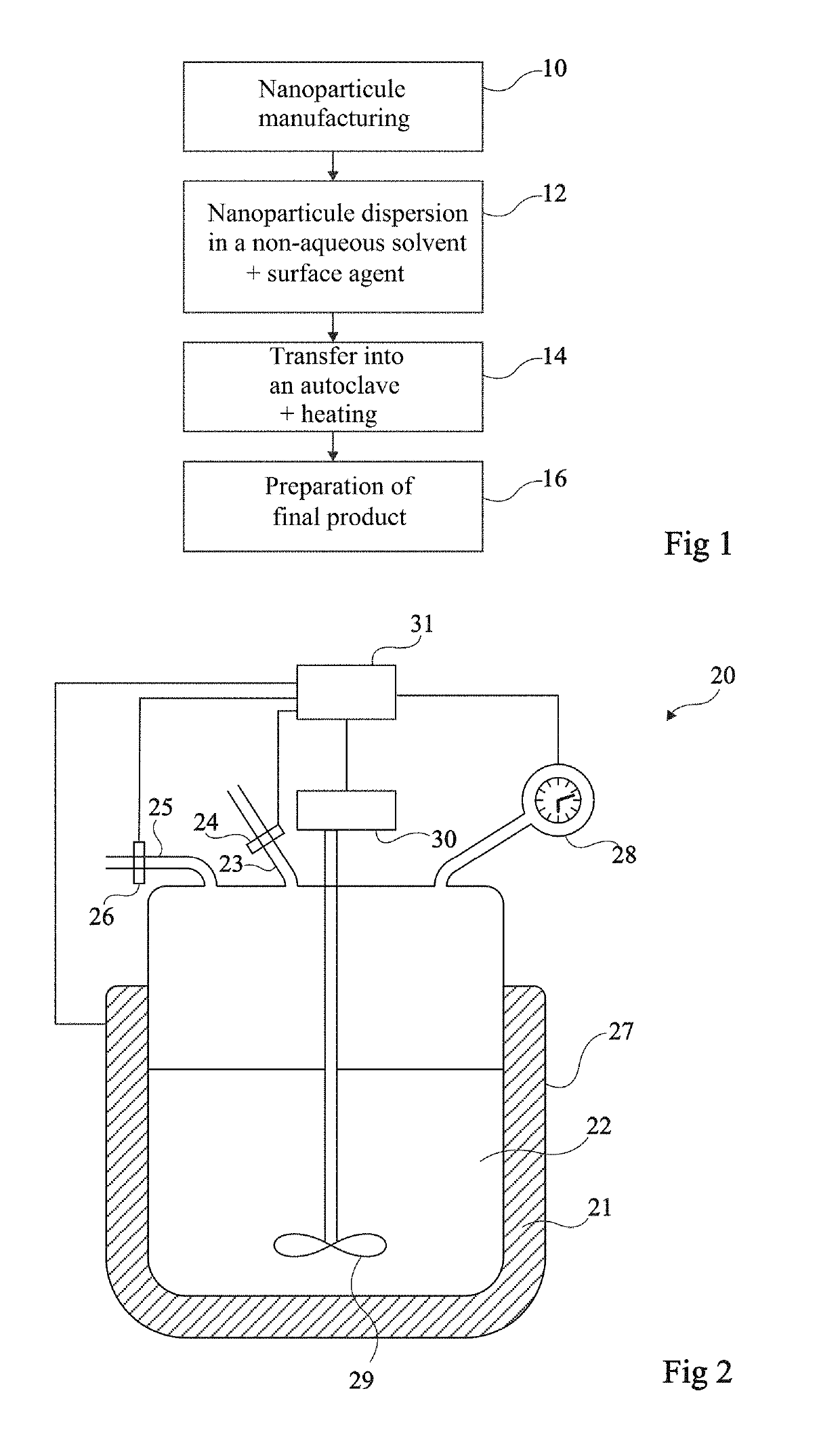
[0141]A milling step has been carried out. A functionalization step has been carried out. For the functionalization step, the solvent was ethanol and the coupling agent was trimethoxyoctadecylsilane (TMODS, Sigma Aldrich). The nanoparticle concentration has been adjusted to 35 mg / ml of ethanol. The mass ratio between the nanoparticles and the coupling agent was 1:1. The dispersion has been placed in an autoclave for 17 hours at 150° C. at a pressure from 20 bars to 30 bars.
[0142]The nanoparticle powder has been recovered after the step of functionalization by the addition of ethanol (antisolvent) in excess. The addition of ethanol causes a very fast decantation of the particles. This is a proof that the particle surface has become hydrophobic after the treatment in the autoclave in the presence of TMODS. A dispersion of the powder of functionalized nanoparticles has been achieved in 1,2-...
example 5
[0148]The YAG:Ce3+ microparticle powder of example 1 has been used to form a nanoparticle powder.
[0149]A milling step has been carried out. A functionalization step has been carried out. For the functionalization step, the solvent was ethanol and the coupling agent was (3-glycidoxypropyl)trimethoxysilane (GPTMS, Sigma Aldrich). The nanoparticle concentration has been adjusted to 50 mg / ml of ethanol. The mass ratio between the nanoparticles and the coupling agent was 1:1. The dispersion has been placed in an autoclave for 25 hours at 150° C. and at a pressure from 20 bars to 30 bars.
[0150]The nanoparticle powder has been recovered after the functionalization step by centrifugation. A dispersion of the powder of functionalized nanoparticles has been achieved in diethylene glycol diethyl ether, which is a polar solvent.
[0151]FIG. 15 shows the particle size curve of the YAG:Ce3+ nanoparticle powder obtained after the functionalization step. This curve is close to the curve of FIG. 11.
[0...
example 6
[0154]The YAG:Ce3+ microparticle powder of example 1 has been used to form a nanoparticle powder.
[0155]A milling step has been carried out. A pretreatment step has been carried out, where the nanoparticle dispersion obtained at the milling step has been mixed with TEOS and with an aqueous solution with 30% of ammonia (NH4OH). The mixture is then heated at 70° C. for 7 hours. The photoluminescent nanoparticle concentration has been adjusted to 18 mg / ml. The volume ratio between the ammonia solution and the TEOS was 0.5 ml of TEOS / 0.4 ml of NH4OH. The SiO2 mass after a full hydrolysis / condensation of TEOS amounts to approximately 5% of the photoluminescent nanoparticle mass. A functionalization step has then been carried out. For the functionalization step, the solvent was ethanol and the coupling agent was (3-trimethoxysilyl)propyl methacrylate (TMSPMA, Sigma Aldrich). The photoluminescent nanoparticle concentration has been adjusted to 30 mg / ml of ethanol. The mass ratio between the...
PUM
| Property | Measurement | Unit |
|---|---|---|
| pressure | aaaaa | aaaaa |
| size | aaaaa | aaaaa |
| temperature | aaaaa | aaaaa |
Abstract
Description
Claims
Application Information