Low-pressure drop structure of particle adsorbent bed for improved adsorption gas separation process

a particle adsorbent and gas separation technology, which is applied in the direction of gas treatment, dispersed particle separation, membrane technology, etc., can solve the problems of uneconomical system, increased pressure drop, and inability to arrange in a conventional packed bed column or fluidized bed with a length of typically several ten centimeters to several meters, and achieve good corrosion resistance

Active Publication Date: 2019-08-22
CLIMEWORKS
View PDF0 Cites 2 Cited by
  • Summary
  • Abstract
  • Description
  • Claims
  • Application Information

AI Technical Summary

Benefits of technology

[0044]Using aluminum inter alia has the advantage of good corrosion resistance while enabling lightweight construction.
[0045]By providing this structure the grid structure protects the flexible fabric layer from the sharp edges of the metal sheets of the heat exchange element on both sides thereof. As concerns the bottom further grid structure being the outermost layer this is provided to avoid sagging of the lower flexible fabric layer.

Problems solved by technology

The requirement on the pressure drop can become even more severe, if trace components are removed from a gas stream.
In particular, all DAC approaches have one major challenge in common which are the very large air volumes that have to be passed through any capture system in order to extract a certain amount of CO2 from the air.
Otherwise the energy requirements for air pumping will render the system uneconomical.
While many materials that have promising properties for a DAC process are typically in a granular form, their arrangement in a conventional packed bed column or in a fluidized bed with a length of typically several ten centimeters to several meters will usually not be feasible, since the resulting pressure drops will exceed the tolerable limits by one or several orders of magnitude.

Method used


Image

  • Low-pressure drop structure of particle adsorbent bed for improved adsorption gas separation process
  • Low-pressure drop structure of particle adsorbent bed for improved adsorption gas separation process
  • Low-pressure drop structure of particle adsorbent bed for improved adsorption gas separation process

Examples


Embodiment Construction

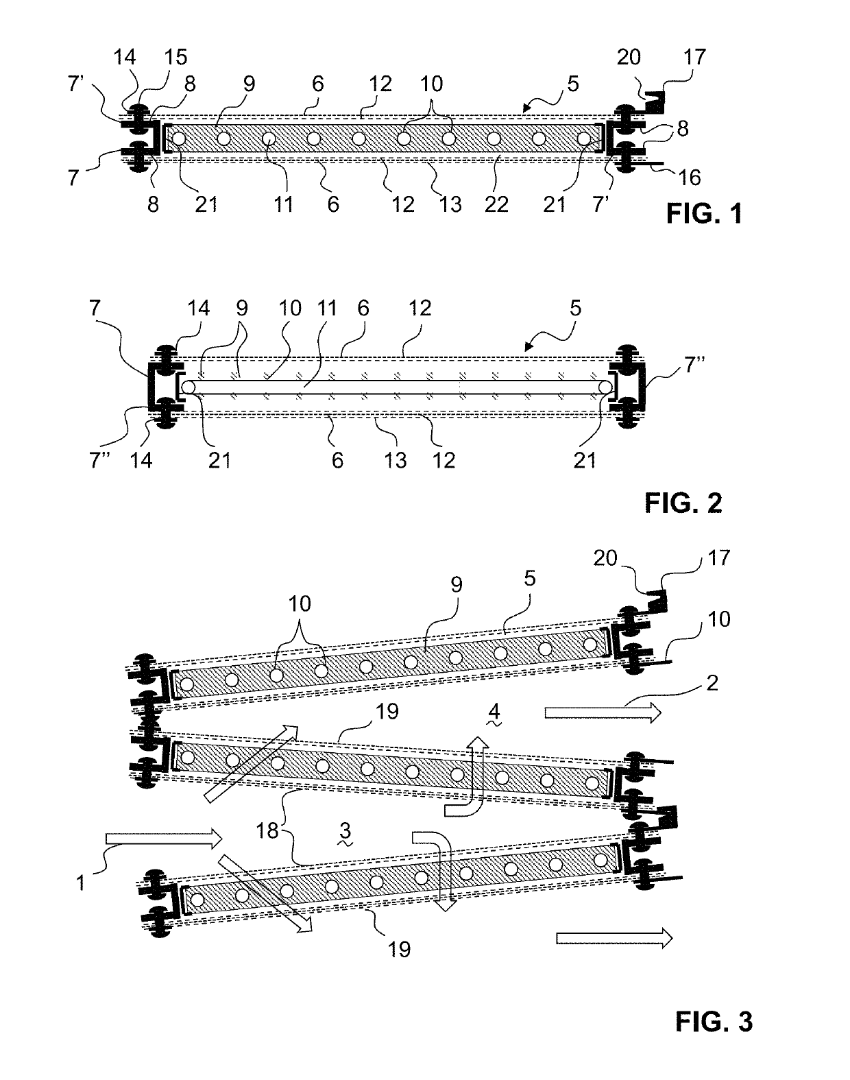
[0106]FIG. 1 shows a schematic cut through a particular absorbent structure layer element 5 in the horizontal orientation with heat exchange element, said cut being along a direction perpendicular to the running direction of the heat exchange tubes 11. FIG. 2 shows the corresponding cut in a direction perpendicular to the one as shown in FIG. 1. It should be noted that the running direction of the heat exchange element tubes 11 can also be different, i.e. it is also possible that the heat exchange element 22 is rotated by 90 degrees within the frame structure.

[0107]There is provided a rigid rectangular frame structure formed by two pairs of mutually parallel frame profiles 7′ and 7″. One first pair 7′ is each provided as a U-shaped aluminum profile with the groove of the corresponding U-shape facing outwardly (see FIG. 1). So the two legs 8 of the corresponding profile 7 are facing outwardly and are arranged parallel to the main plane of the corresponding layer 5.

[0108]The other pai...


PUM


Abstract

A gas separation unit for the separation of a first gas from a mixture containing said first gas as well as further gases by a cyclic adsorption/desorption process using a loose particulate sorbent material for gas adsorption. The particulate sorbent material is arranged in at least two stacked layers (5) that are mounted on a stiff rectangular circumferential frame (7). A plurality of tubes (11) is provided for a heat exchange fluid within the frame (7). The tubes (11) are in thermal contact with a plurality of sheets (9) of metal which are arranged essentially perpendicular to a main plane of the frame (7) and perpendicular to the tubes (11). The sheets (9) extend in a continuous manner between a first pair of mutually parallel metal profiles (7′) and are provided with a plurality of holes (10) through which the plurality of tubes (11) penetrate.

Description

TECHNICAL FIELD[0001]The present invention relates to sorbent bed structures for gas separation processes and the use of such structures for gas separation, for example for the separation / capture of CO2 from gas streams.PRIOR ART[0002]Gas separation by adsorption has many different applications in industry, for example removing a specific component from a gas stream, where the desired product can either be the component removed from the stream, the remaining depleted stream, or both. Thereby both, trace components as well as major components of the gas stream can be targeted by the adsorption process.[0003]One important application is capturing carbon dioxide (CO2) from gas streams, e.g., from flue gases, exhaust gases, industrial waste gases, biogas or atmospheric air.[0004]Capturing CO2 directly from the atmosphere, referred to as direct air capture (DAC), is one of several means of mitigating anthropogenic greenhouse gas emissions and has attractive economic perspectives as a non...

Claims


Application Information

Patent Timeline
Patent Type & Authority Applications(United States)
IPC IPC(8): B01D53/04
CPCB01D53/0438B01D53/0462B01D2257/504B01D53/0407Y02C20/40
Inventor WURZBACHER, JAN ANDRÉREPOND, NICOLASRUESCH, TOBIASSAUERBECK, SEBASTIANGEBALD, CHRISTOPH
Owner CLIMEWORKS
Why Eureka
Try Eureka