
Control electronics for brushless motors

a technology of control electronics and motors, applied in the direction of electric generator control, dynamo-electric converter control, dynamo-electric gear control, etc., can solve the problem that the control method has the disadvantage of fitting hall sensors (including components and assembly costs), and achieve the effect of improving electric efficiency

Inactive Publication Date: 2019-10-31
THOR POWER
View PDF0 Cites 0 Cited by
  • Summary
  • Abstract
  • Description
  • Claims
  • Application Information

AI Technical Summary

Benefits of technology

The invention provides better electric efficiency for controlling brushless motors, which are used in a variety of applications such as air conditioners, refrigerators, and power tools. The controlling electronics use microcontrollers and other efficient components to electronically control the motor. The control electronics adapt to the challenging high power, high speed, and high performance motor application, allowing for maximum motor speed and high load capabilities. The invention also includes soft start for smooth motor start-up and vector control for smooth torque profile. The comprehensive control software is developed for motor-specific applications and is achieved with a low-cost processor.

Problems solved by technology

This control method has the disadvantage of fitting the hall sensors (including components and assembly costs).

Method used


Image

  • Control electronics for brushless motors
  • Control electronics for brushless motors
  • Control electronics for brushless motors

Examples


Embodiment Construction

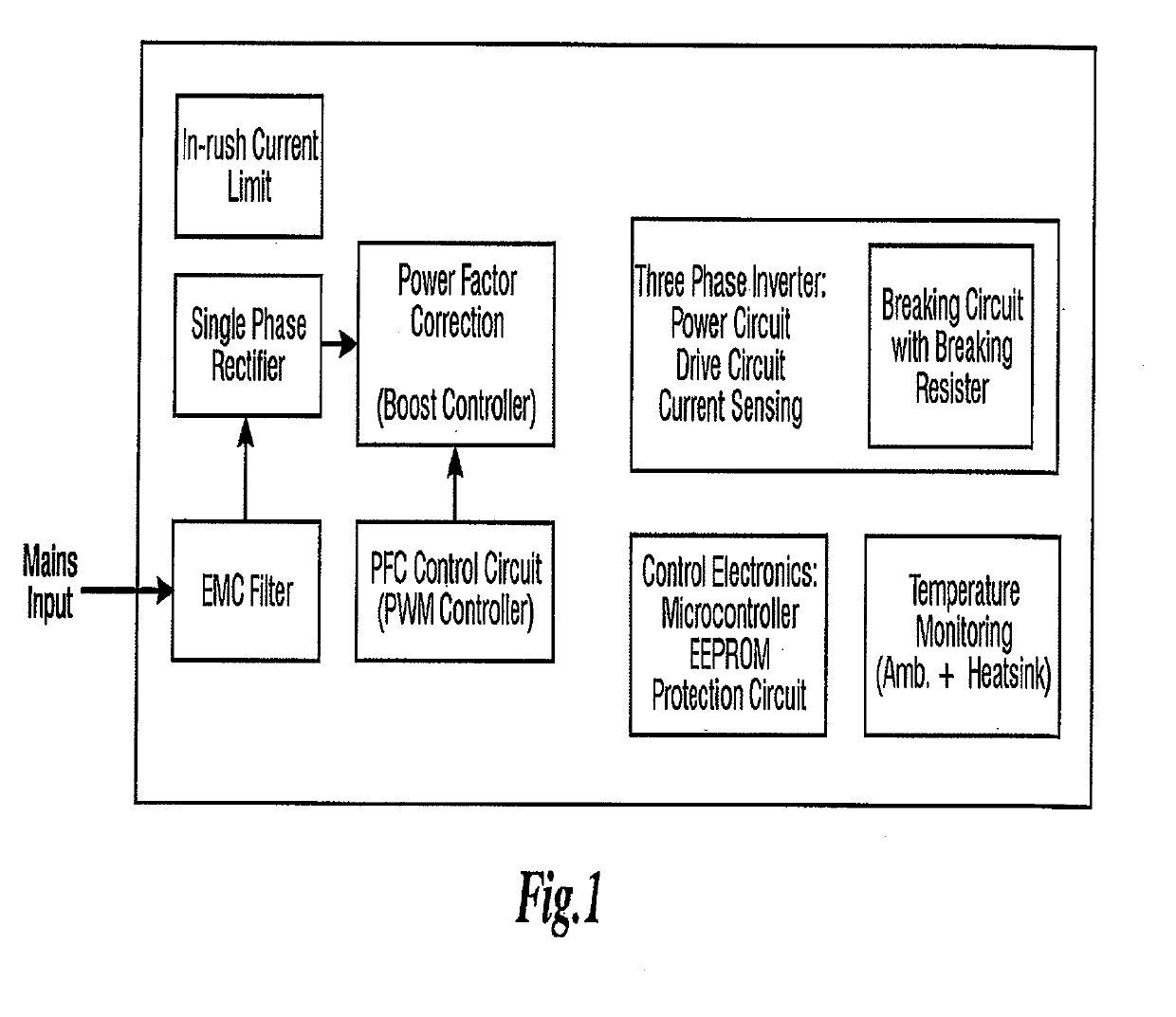
[0023]The invention encompasses several preferred embodiments of control electronics for brushless motors. The major building blocks of one preferred embodiment of the control electronics are shown in FIG. 1 and described below and in the parent patent applications that are incorporated herein by reference in their entirety.

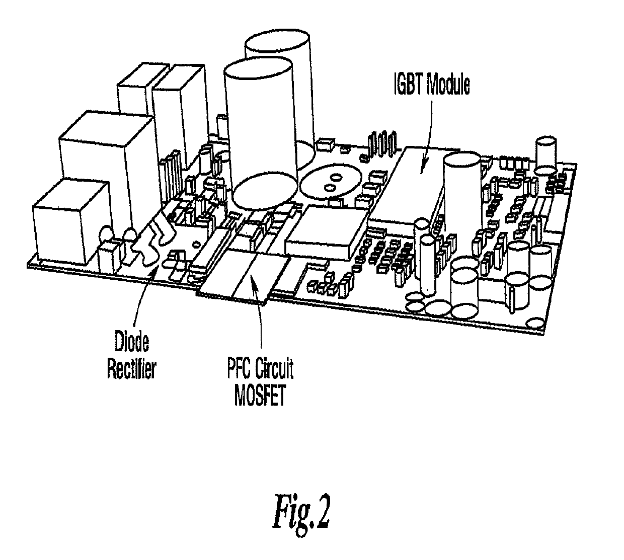
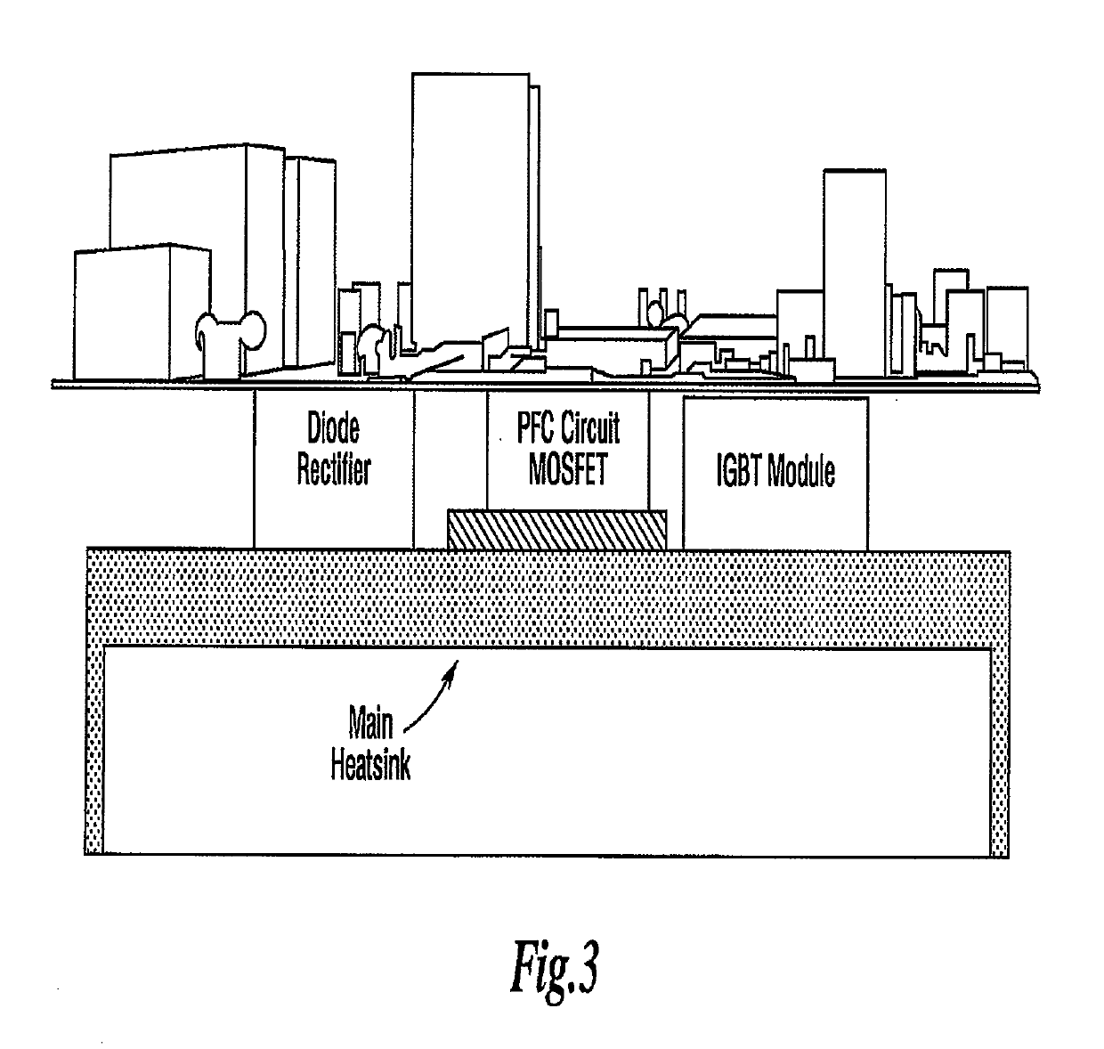
[0024]A very high power density is achieved by configuring all of the control electronics on a single printed circuit board. Optimally, the electronics are separated and divided into two parts. On the left side, there is input power control circuitry connected by a DC link to control circuitry and power output circuitry on the right side. A perspective view of an example layout implementation is shown in FIG. 2. The diode rectifier module, PFC Circuit MOSFET elements, and IGBT module dissipate the most amount of heat and the approximate location of these parts are shown in FIGS. 2 and 3. These parts are preferably located on the bottom side of the printed circuit...


PUM


Abstract

An electronic control circuit for a brushless motor has an input power circuit providing a DC voltage and a microcontroller integrated circuit receiving the DC voltage. The microcontroller integrated circuit provides three-phase control signals according to a space vector control method. A microprocessor connected to the microcontroller integrated circuit executes supervisory control over the electronic control circuit. An inverter circuit receives the three-phase control signals from the microcontroller integrated circuit and provides driving signals to the brushless motor based on the three-phase control signals received from the microcontroller integrated circuit.

Description

RELATED APPLICATIONS[0001]This application claims priority to U.S. patent application Ser. No. 11 / 469,023 filed on Aug. 31, 2006, which in turned claimed priority to U.S. Provisional Patent Application Ser. No. 60 / 712,945 filed on Aug. 31, 2005 and U.S. Provisional Patent Application Ser. No. 60 / 725,775 filed on Oct. 11, 2005. The contents of all of these parent patent applications are hereby incorporated by reference in their entirety.FIELD OF THE INVENTION[0002]The invention relates generally to control electronics for brushless motors. In particular, the invention relates to the application of one or more micro controllers to control a brushless motor.BACKGROUND OF THE INVENTION[0003]The US Department of Energy has estimated that alternating current motors consume more than 65% of the electricity produced and total electricity sales in the US will increase at an average annual rate of 1.9%, from 3,481 billion kilowatt hours in 2001 to 5,220 billion kilowatt hours in 2025. With a ...

Claims


Application Information

Patent Timeline
Patent Type & Authority Applications(United States)
IPC IPC(8): H02P27/06H02P23/00H02P21/22
CPCH02P27/06H02P21/22H02P23/0077H02P6/085H02P23/26
Inventor BONNER, DAVIDXU, AIDONG
Owner THOR POWER
Learn More