
Non-invasive optical measurement system and method for neural decoding

a neural decoding and optical measurement technology, applied in the field of non-invasive optical measurement systems and neural decoding, can solve the problems of limited spatial resolution of conventional optical detectors, limited usable penetration depths, and order of centimeters, and achieves improved temporal sensitivity to fast optical signals, simple and less expensive

Active Publication Date: 2019-11-07
HI LLC
View PDF0 Cites 15 Cited by
  • Summary
  • Abstract
  • Description
  • Claims
  • Application Information

AI Technical Summary

Benefits of technology

The present invention provides a non-invasive optical measurement system and method for measuring physiological events in an anatomical structure, such as brain activity, using a continuous wave (CW) optical source and an interferometer. The system generates source light and delivers it into the anatomical structure, where it is scattered by the anatomical structure and exits as physiological-encoded signal light. The system detects the phase-modulated interference light patterns created by the scattered light and combines them to create a time-lapsed complex field of the physiological-encoded signal light. The system then measures the decorrelation speed of the complex field over a period of time to identify a physiological event. The technical effects of the invention include the ability to measure brain activity non-invasively and with high accuracy, providing a non-invasive optical measurement system and method for measuring physiological events in anatomical structures.

Problems solved by technology

However, because optical imaging techniques rely on light, which scatters many times inside brain, skull, dura, pia, and skin tissues, the light paths occurring in these techniques comprise random or “diffusive” walks, and therefore, only limited spatial resolution can be obtained by a conventional optical detector, often on the order of centimeters, with usable penetration depths being limited to a few millimeters.
The reason for this limited spatial resolution is that the paths of photons striking the detector in such schemes are highly variable and difficult, and even impossible, to predict without detailed microscopic knowledge of the scattering characteristics of the brain volume of interest, which is typically unavailable in practice (i.e., in the setting of non-invasive measurements through skull for detecting neural activity in the brain for brain-computer interfacing).
In summary, light scattering has presented challenges for optical detection techniques in achieving high spatial resolution inside tissue regions at depths below a user's skull, e.g., multiple centimeters.
Moreover, the diffusive nature of light propagation also creates challenges for measurements of fast changes in optical scattering inside tissue, since essentially all paths between source and detector are highly scattered to begin with.
Regardless of the type, the depth at which a traditional OCT system images biological tissue is limited, because at greater depths the proportion of light that escapes without scattering (i.e., the ballistic light) is too small to be detected.
Thus, the clinical applications of a traditional OCT system have, thus far, been limited to imaging sub-surface features, such as obtaining high-resolution ophthalmic images of the retina.
As such, traditional OCT systems are presently insufficient for measuring neural activity in the regions of the brain at deeper depths (i.e., deeper than 2 mm).
However, conventional TD NIRS systems require expensive pulsed lasers and complex time-correlated single photon counting detection, making widespread adoption of this technology challenging.
Furthermore, typical TD NIRS systems are somewhat complicated in that they must record the arrival time of photons over the relevant time period in order to acquire the full DTOF, and furthermore, must operate at high enough speeds to record this full DTOF at a high enough resolution to extract the relevant signal.
However, FD NIRS typically does not directly resolve the DTOF, and the modulation / demodulation schemes can be complex and expensive.
However, such fast-sweeping laser source is relatively expensive and is subject to instability due to changes in temperature, thereby compromising its signal-to-noise ratio (SNR).
Furthermore, the iNIRS systems described above have not been demonstrated to measure fast-optical signals, which refers to changes in optical scattering that occur when light propagating through active neural tissue (e.g., active brain tissue) is perturbed through a variety of mechanisms, including, but not limited to, cell swelling, cell volume change, changes in membrane potential, changes in membrane geometry, ion redistribution, birefringence changes, etc.
However, fast-optical signals are very small (on the order of 1 / 1000 for intensity measurements and picoseconds or fractions thereof for phase delay measurement), and thus, there is a challenge separating fast-optical signals from background noise.
The disadvantage of this is, of course, the requirement that multiple measurements would need to be taken to detect a fast-optical signal, limiting applicability for “real time” applications, e.g., brain-computer interfacing.
Also, like the iNIRS systems described above, the DCS techniques have not been demonstrated to measure fast-optical signals.
It is believed the signal-to-noise (SNR) of DCS measurements, and thus the temporal sensitivity of DCS techniques to fast-optical signals, may be too low to enable effective measurement of fast-optical signals.

Method used


Image

  • Non-invasive optical measurement system and method for neural decoding
  • Non-invasive optical measurement system and method for neural decoding
  • Non-invasive optical measurement system and method for neural decoding

Examples


Embodiment Construction

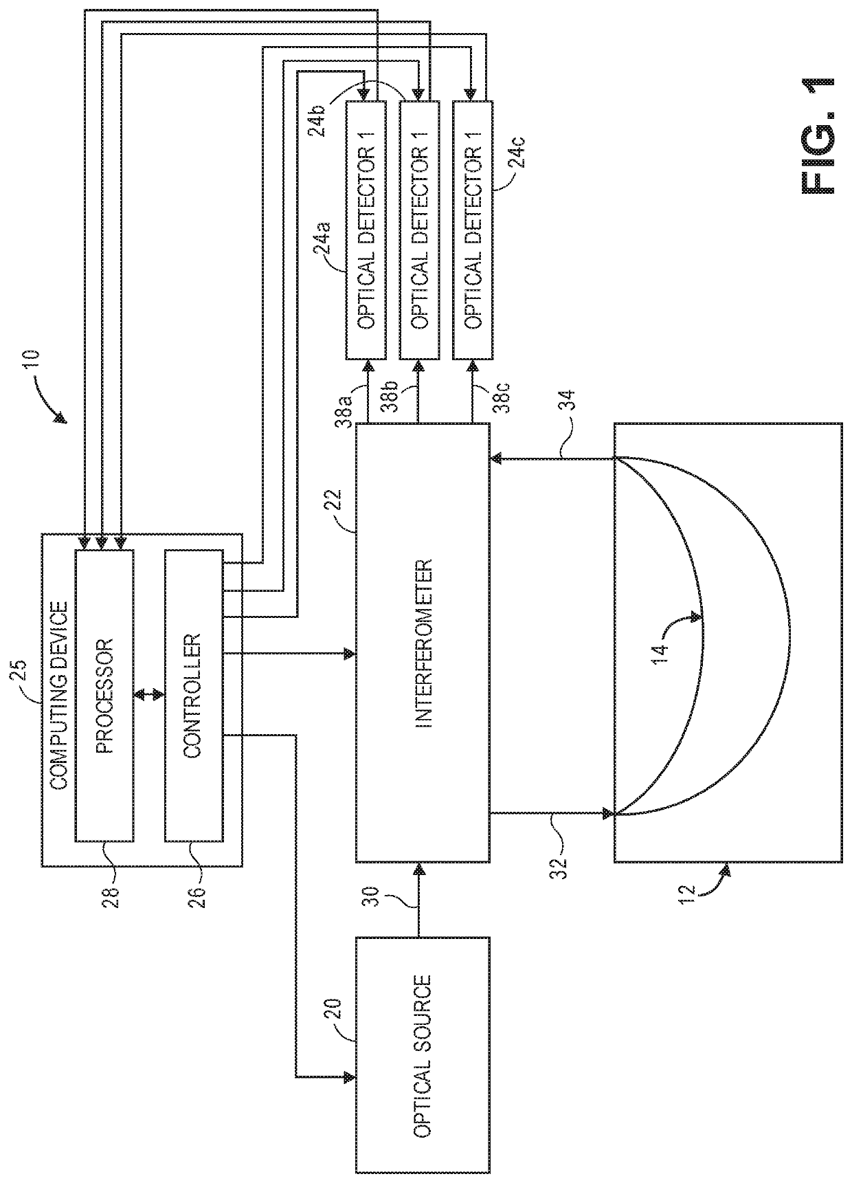
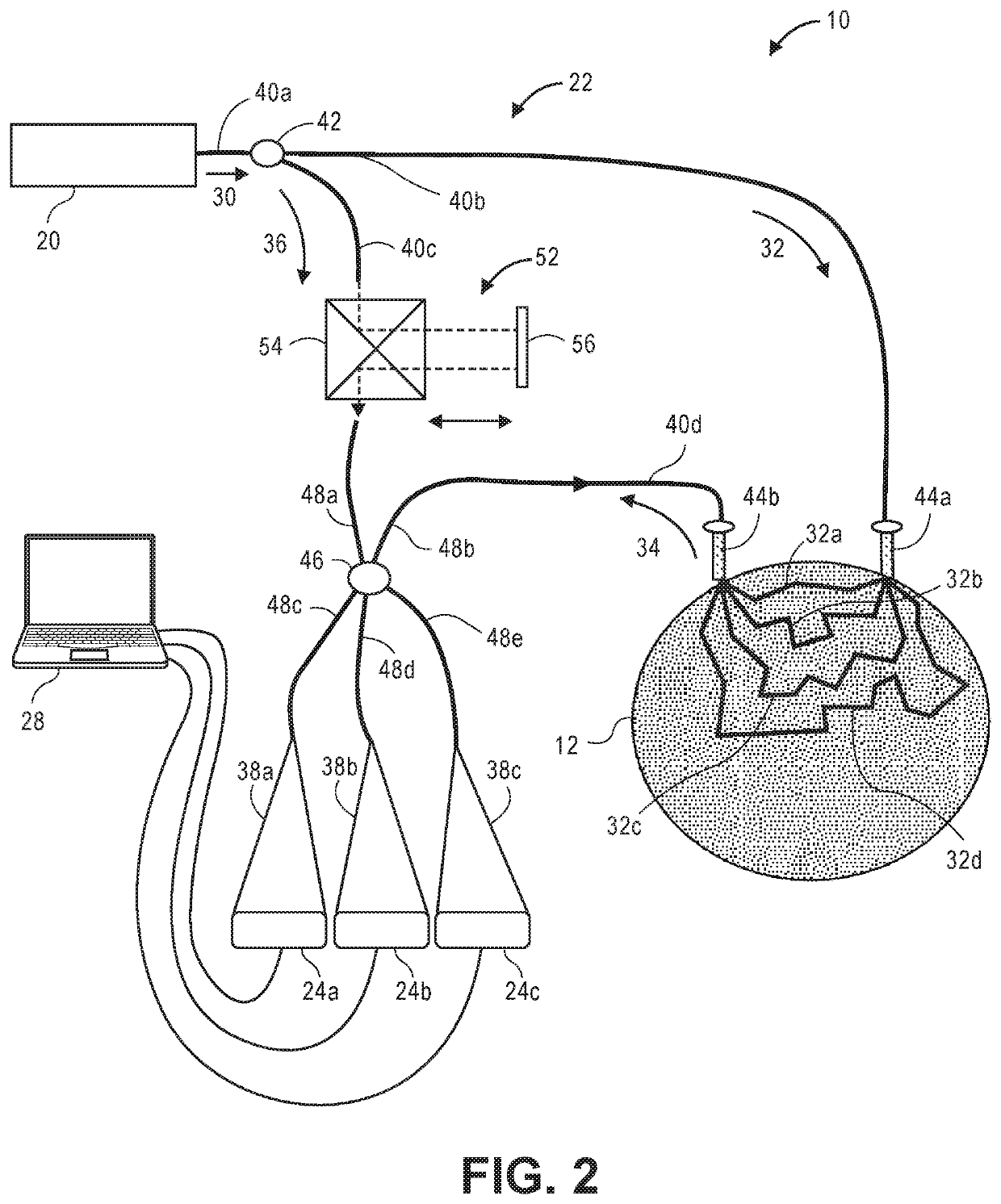
[0040]Referring now to FIG. 1, a generalized embodiment of an optical measurement system 10 constructed in accordance with the present inventions will be described. The optical measurement system 10 is a holographic optical system (i.e., a system that mixes detected signal light against reference light in order to increase the signal-to-noise ratio (SNR) of the relevant signal). As such, the optical measurement system 10 focuses on the measurement of multiple-scattered signal light of a depth-correlated optical path length, and is capable of detecting physiological events in tissue at a penetration depth of multiple centimeters, as opposed to ballistic signal light measured by a traditional Optical Coherence Tomography (OCT) system.

[0041]The optical measurement system 10 utilizes a simple and relatively inexpensive, low coherence, continuous wave (CW) source, in contrast to the pulsed laser or swept laser respectively required by TD-NIRS and FD-NIRS systems (see Background section)....


PUM


Abstract

A non-invasive optical measurement system comprises an optical source for generating source light, and an interferometer for splitting the source light into sample light and reference light, delivering the sample light into an anatomical structure, resulting in physiological-encoded signal light that exits the anatomical structure, and combining the signal light and the reference light into at least three phase-modulated interference light patterns. The optical path lengths of the respective source light and sample light match within a coherence length of the source light. The system further comprises at least three optical detectors configured for respectively detecting the interference light patterns, and a processor configured for determining a time-lapsed complex field of the signal light based on the interference light patterns, determining a decorrelation speed of the time-lapsed complex field of the signal light, and identifying a physiological event in the anatomical structure based on the determined decorrelation speed of the signal light.

Description

RELATED APPLICATION DATA[0001]Pursuant to 35 U.S.C. § 119(e), this application claims the benefit of U.S. Provisional Patent Application 62 / 666,978, filed May 4, 2018, and U.S. Provisional Patent Application 62 / 740,814, filed Oct. 3, 2018, which are expressly incorporated herein by reference.FIELD OF THE INVENTION[0002]The present inventions relate to methods and systems for non-invasive measurements in the human body, and in particular, methods and systems related to detecting physiologically-dependent optical parameters in the human body, e.g., the brain.BACKGROUND OF THE INVENTION[0003]Measuring neural activity in the brain is useful for medical diagnostics, neuromodulation therapies, neuroengineering, or brain-computer interfacing.[0004]Conventional methods for measuring neural activity in the brain include diffusive optical imaging techniques, which employ moderate amounts of near-infrared or visible light radiation, thus being comparatively safe and gentle for a biological sub...

Claims


Application Information

Patent Timeline
IPC IPC(8): A61B5/00A61B5/04
CPCA61B5/0075A61B5/0064A61B5/0261A61B5/04001A61B2576/026A61B5/0077A61B5/0042A61B5/4064A61B5/0066A61B5/7257A61B5/24G16H30/40
Inventor ZHOU, HAOJIANGHORSTMEYER, ROARKERUAN, HAOWENSHEN, YUECHENGALFORD, JAMU
Owner HI LLC
Learn More