Assembly for Increasing the Resolution of a Laser Scanning Microscope

a laser scanning microscope and resolution technology, applied in the field of assembly for increasing the resolution of laser scanning microscopes, can solve the problems of difficult use of the above-described iii methods in the microscope, complicated methods, etc., and achieve the effects of low production cost, convenient adjustment, and easy operation

Active Publication Date: 2020-01-23
CARL ZEISS MICROSCOPY GMBH
View PDF0 Cites 3 Cited by
  • Summary
  • Abstract
  • Description
  • Claims
  • Application Information

AI Technical Summary

Benefits of technology

[0045]The invention explained above yields a simple realization of half pupil image inversion interference (HP-III), which facilitates an adjustment that is both easy to carry out and also very stable, and which moreover has low production costs. The specific prism arrangement of the III double wedge prism has already been specified above.
[0046]The arrangement according to the invention facilitates a simplified solution for increasing the resolution in laser scanning microscopes (LSM) by way of image inversion interferometry (III...

Problems solved by technology

All above-described III methods are very complicated above all in terms of adjustment an...

Method used


Image

  • Assembly for Increasing the Resolution of a Laser Scanning Microscope
  • Assembly for Increasing the Resolution of a Laser Scanning Microscope
  • Assembly for Increasing the Resolution of a Laser Scanning Microscope

Examples


Embodiment Construction

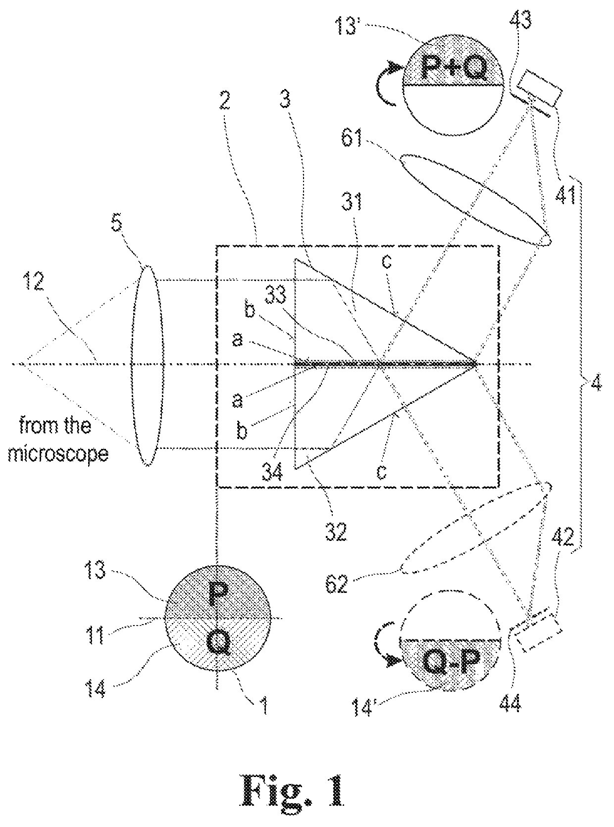
[0059]The invention, intended to be referred to as half pupil image inversion interferometry (HP-III) on account of the preferred embodiment, is illustrated in FIG. 1 for a confocal laser scanning microscope (LSM), wherein a pupil 1 of the detection beam path of the LSM is coupled into a shortened common path interferometer 2, which is shown in a basic version with a double wedge prism 3 (also referred to as HP-III prism below), and imaged on at least one optoelectronic receiver 4. For the benefit of the typical confocal evaluation of the LSM, respectively one pinhole 43 or 44 is preferably arranged in front of a first detector 41 and, where applicable, a second detector 42. In the one-dimensional case (line scan), the pinhole can ideally be a line pinhole (not plotted) that is matched to the line illumination, i.e., has a slot in place of a hole. Then, the receiver 4 would ideally be a linear detector 41 (line detector), which resolves the line with spatial resolution in the image ...


PUM


Abstract

An arrangement for increasing resolution of a laser scanning microscope has a simplified adjustment and lower susceptibility to errors. The pupil beam from the laser scanning microscope is coupled into a shortened common path interferometer, to make wavefronts of a pupil image mirrored at at least one axis and wavefronts of an unchanged pupil image interfere. The area of a pupil from the pupil beam is split into two complementary portions P and Q producing two partial beams separately supplied to at least one beam deflection means by total-internal reflection along the common path interferometer. The light of the interferometer branches from transmitted light of the one interferometer branch and reflected light of the other interferometer branch is made to interfere at a partly transmissive beam splitter layer to cause constructive interference C and destructive interference D of the wavefronts from the two different portions P and Q of the pupil.

Description

RELATED APPLICATIONS[0001]This Application is a U.S. National Stage Under 35 USC § 371 of International Application PCT / DE2018 / 100060, filed on Jan. 25, 2018, which in turn claims priority to German Patent Application DE 10 2017 101 829.8, filed Jan. 31, 2017, both of which are incorporated herein by reference in their entirety.FIELD OF THE INVENTION[0002]The invention relates to an arrangement for increasing the resolution of a laser scanning microscope (LSM), in particular for conventional and confocal laser scanning microscopes (CLSM).[0003]Moreover, use in an LSM with a spatially resolving detector, preferably when processing microscopic images in conjunction with an airy scan system, is of particular interest.BACKGROUND OF THE INVENTION[0004]High-resolution laser scanning microscopes are increasingly important aids for diagnostics, laser surgery and research in medicine and biology as electron-microscopic and predominantly UV-radiation-based processing and examination methods a...

Claims


Application Information

Patent Timeline
IPC IPC(8): G02B21/00G02B27/10G02B27/12
CPCG02B27/126G02B21/0072G02B21/0056G02B27/1066G02B21/00
Inventor WICKER, KAINETZ, RALF
Owner CARL ZEISS MICROSCOPY GMBH
Why Eureka
Try Eureka