Device for insertion into nervous tissue

a technology for nerves and vascular tissues, applied in the field of diagnostic and/or therapeutic devices for insertion into soft tissues, can solve the problems of accompanied damage to the tissue of insertion of microelectrodes or other devices into soft tissues, in particular nervous or endocrinological tissues, and achieve the effect of protecting the tissue from damage and lowering the temperature of soft tissu

Active Publication Date: 2020-03-26
NEURONANO AB
View PDF1 Cites 2 Cited by
  • Summary
  • Abstract
  • Description
  • Claims
  • Application Information

AI Technical Summary

Benefits of technology

[0008]The present invention is based on the insight that dissolution of gels formed by contact of gel forming biocompatible agents, in particular gelatin, with aqueous body fluids in a warm-blooded person or animal can be delayed by lowering the temperature at the contact site.
[0009]In addition, the present invention is based on the insight that lowering the temperature of soft tissue in contact with a medical device being inserted into it protects the tissue from damage. According to the invention the temperature of the tissue contacted by a device being inserted to it is cooled by the device, which has a temperature substantially below tissue temperature, such as a temperature of 30° C. or more, in particular of 40° C. or more below tissue temperature.
[0010]Gel forming biocompatible agents are useful in the implantation of medical devices such as microelectrodes into soft tissue such as nervous or endocrine tissue. The gel forming agents are applied in form of single or multiple layers on the devices forming coats swelling in contact with aqueous body fluid and then dissolving in the fluid or dissolving in the fluid upon degradation. Insertion of medical devices coated in this manner into soft tissue, in particular nervous or endocrine tissue, protects the tissue from damage. A moderate reduction of the temperature at the implantation site by, for instance, 5° C. or 10° C. or 15° C. is often sufficient to substantially delay dissolution of the gel, such as by a time factor of 2 or more.
[0025]According to a preferred embodiment of the invention a proximal portion of the device in a state immediately prior to insertion or later is at a lower temperature than a distal portion thereof so as to function as a heat sink for the distal portion, thereby delaying the warming thereof.

Problems solved by technology

The insertion of microelectrodes or other devices into soft tissue, in particular nervous or endocrinous tissue, is accompanied by damage to the tissue.
A problem with friction reducing materials designed to dissolve in body fluid during and upon insertion is to control their premature dissolution or detachment during insertion.

Method used


Image

  • Device for insertion into nervous tissue
  • Device for insertion into nervous tissue
  • Device for insertion into nervous tissue

Examples


example 1

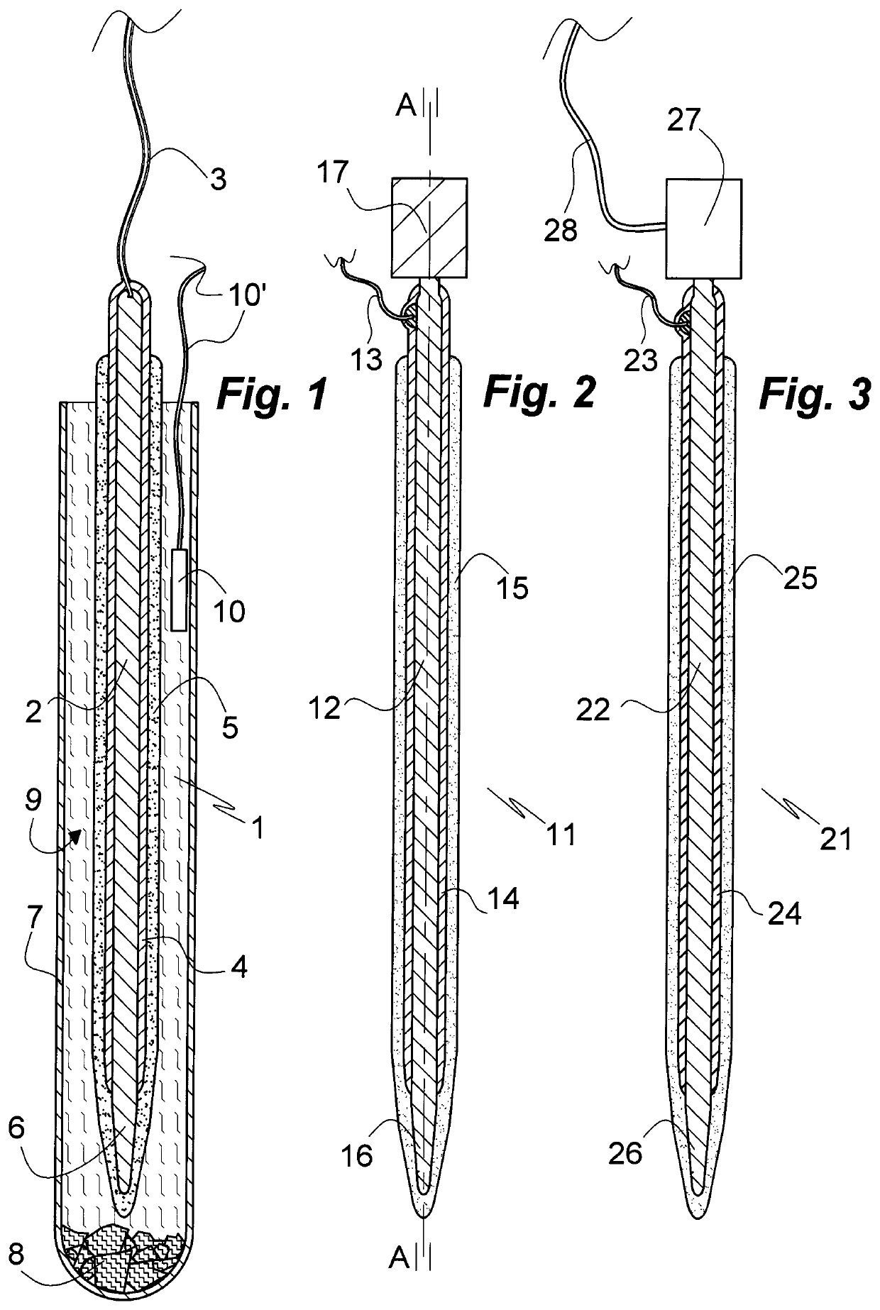
[0090]FIG. 1 illustrates a microelectrode of the art 1 comprising an oblong cylindrical metallic electrode body 2, for instance of silver, gold, platinum or iridium, with a narrowing distal tip 6 and a flexible electrical lead 3 attached to its distal end. Except for the tip 6 the electrode body 2 is electrically insulated by a layer 4 of a polymer material such as polyurethane or Parylene C. Except for a portion extending from the proximal end the electrode body 2 and the tip 6 is covered with a layer 5 of dry gelatin of a Bloom strength of 120. The electrode 1 is shown inserted in a cooling vessel 7 of the shape of a test tube with its distal tip 6 foremost. The vessel 7, which may be thermally insulated (not shown) is loaded with dry ice 8 disposed at the bottom thereof. The electrode 1 is cooled by gaseous carbon dioxide 9 evaporated from the dry ice 8. The temperature of the carbon dioxide 9 atmosphere in the vessel is monitored by a thermocouple 10; alternatively or additional...

example 2

[0092]The design of the microelectrode of the invention 11 shown in FIG. 2 in an axial section A-A substantially corresponds to that of the microelectrode 1 of Example 1 except for a cooling means in form of heat sink 17 attached to the electrode body 12 at its proximal end in a thermally communicating manner. Prior to implantation of the microelectrode 11 the heat sink 17 is cooled in combination with the electrode 11 or separately to a low temperature, such as the temperature to which the electrode 11 is cooled or to an even lower temperature or substantially lower temperature. With the heat sink 17 at a lower temperature than the electrode 11 heat flows from the electrode body 12 to the heat sink 17 thereby cooling the electrode 11 and thus, when being contacted by body fluid, delaying swelling and dissolution of the gelatinous or other swellable layer 15 on an insulating layer 14 covering most of the electrode body 12. Suitable heat sink materials comprise steel, copper, chromiu...

example 3

[0093]The design of the microelectrode of the invention 21 shown in FIG. 3 in an axial section corresponding to axial section A-A of the embodiment of FIG. 2 substantially corresponds to that of the microelectrode 11 of Example 2 except for a cooling means in form of a Peltier element 27 being attached to the electrode body 22 at its proximal end in a thermally communicating manner instead of a heat sink. The Peltier element 27 is energized via an insulated flexible electric lead 28. The microelectrode 21 comprises correspondingly disposed insulating and swellable layers 24, 25 on the electrode body 22, the narrowing distal terminal portion 26 of which is similarly free of insulation 24. The electrode body 22 is electrically connected with a power source (not shown) and / or an instrument for detecting voltage variations (not shown) by means of an electrically insulated flexible lead 23. Upon completion of the insertion procedure the cooled tissue can be brought to body temperature by...


PUM


Abstract

A device selected from microelectrode, temperature sensor, optical sensor, optical fibre, temperature control element, and microdialysis probe for insertion into soft tissue comprises a body with a distal terminal section and a layer of an agent such as gelatin capable of forming a gel with aqueous body fluid on the terminal section. The terminal section and the gel-forming layer have a temperature of more than 30° C. below body temperature during a period of time prior and up to insertion. Also disclosed is method of insertion, an insertion assembly and a use of the device.

Description

FIELD OF THE INVENTION[0001]The present invention relates to a diagnostic and / or therapeutic device for insertion into soft tissue, in particular nervous or endocrinous tissue, to an insertion assembly comprising the device and insertion means, to methods of insertion of the device into nervous tissue, and to uses thereof. A preferred embodiment of the device is a microelectrode. Other embodiments of the device are temperature and optical sensors, optical fibres, temperature control elements, microdialysis probes, and the like.BACKGROUND OF THE INVENTION[0002]The insertion of microelectrodes or other devices into soft tissue, in particular nervous or endocrinous tissue, is accompanied by damage to the tissue. To ensure proper function of the electrode upon insertion prevention of excessive damage is of paramount importance. Various measures can be taken to minimize damage, such as a design of the microelectrode emphasizing reduction of electrode diameter and provision of a coat of a...

Claims


Application Information

Patent Timeline
Patent Type & Authority Applications(United States)
IPC IPC(8): A61B17/34A61B5/00A61B5/01A61F7/00A61B5/04A61N1/05A61F7/02A61B5/24A61B5/296
CPCA61B17/3468A61F7/02A61F7/007A61N1/0551A61F2007/0219A61B5/0084A61F2007/0075A61B5/04001A61B5/01A61N1/0531A61B5/25A61B2562/0209A61B2560/063A61B5/293A61B5/14528A61F7/00A61F2007/0095A61B5/24A61B5/6877A61N1/05A61N1/3605A61N1/37205A61N1/375A61B2562/16A61B2562/028A61B2562/0271
Inventor SCHOUENBORG, JENS
Owner NEURONANO AB
Why Eureka
Try Eureka