Third rail heater control system

a control system and heater technology, applied in the direction of power rails, railway cleaning, railways, etc., can solve the problems of high voltage inability to control the temperature of the heater, etc., to achieve maximum energy saving, reduce the operational distance of the radio link, and increase the overall robustness of the communication link

Active Publication Date: 2020-08-13
M C DEAN IP LLC
View PDF0 Cites 4 Cited by
  • Summary
  • Abstract
  • Description
  • Claims
  • Application Information

AI Technical Summary

Benefits of technology

[0012]The digital controller includes local relay units at railway stations and / or power substations, each of which includes a radio transceiver in communication with the transceiver of the switch controller, and a master control station located remotely with respect to the local relay units. The master control station is connected to the local relay units via an optical fiber cable. Such architecture minimizes the operational distance of the radio link between the wireless controller and the digital controller, thereby increasing the overall robustness of the communication links of the system.
[0013]The master control station automatically runs a self-diagnostic procedure every time it is started up. Upon initial actuation of the local control units, the master control station first determines whether or not an electrical current is present in the third rail connected to the junction box. Next, it proceeds to test the operability of other components of each of the switching assemblies. Finally, the master control station connects the strip heaters to the electrical current from the third rail in sequential fashion such that the electrical load on the third rail is gradually applied. The master control station also is equipped with precipitation and temperature sensors that monitor the outside weather conditions for ice and snow and will automatically energize the heat tape system. These sensors may be located in multiple places along the rail tracks and operate only the heater sections needed based on the local weather conditions. This provides for fully automatic operation as well as maximum energy savings.

Problems solved by technology

Electrically-powered railway tracks are an inherently dangerous environment.
Such intermittent currents may have voltages high enough (e.g. ˜100 volts) to be life threatening.
Additionally, many maintenance and repair operations (such as the replacement of a burned out ribbon heater, or components within a junction box) are carried out under conditions of snow and ice where the exact location of dangerous rails and connections is concealed, and where the terrain is slippery.
On the negative side, it greatly increases the chances of accidental contact with the 750 volts DC current on either the third rail itself, or on an exposed contact in the junction box.
As a result of such hazardous conditions, electric train maintenance personnel are exposed to a very real danger of accidental electrocution.
While the prior art automatic third rail heater control systems substantially reduce power consumption and costs, the applicant has observed five shortcomings in the design of such systems that render the maintenance and operation unduly hazardous to the operators of such systems.
First, there is no provision in such prior art systems for sensing, recording, and processing the type of data that could accurately predict when a failure condition of a ribbon heater is likely to occur.
Second, the junction boxes containing the control switches often have exposed contacts carrying 750 volts DC from the third rail.
While there may be an internal or external “kill” switch to break the connection of the third rail current to the switching components of the box, a hazardous shock condition will be present if the maintenance operator neglects to open such a switch.
In the case of an internal “kill” switch, the need to locate and to manually operate the switch—which is necessarily close to open contacts carrying the 750 volts DC operating current—can be hazardous, particularly in snowstorm conditions at night.
Thirdly, there is no provision in prior art systems for safely and conveniently powering up the switching assembly for diagnostic purposes when the 750 volts DC from the third rail is cut off.
Fourth, while many prior art systems utilize radio links to communicate switching commands between a central controller and local junction boxes, the strength and reliability of such radio links can be compromised by the distances between the central controller and junction boxes, the EMI generated by the electrical activity in the train stations, and poor weather conditions.
Finally, there is no capacity in prior art systems to periodically self-diagnose in real time order to confirm that all critical components are performing normally.

Method used


Image

  • Third rail heater control system
  • Third rail heater control system
  • Third rail heater control system

Examples


Embodiment Construction

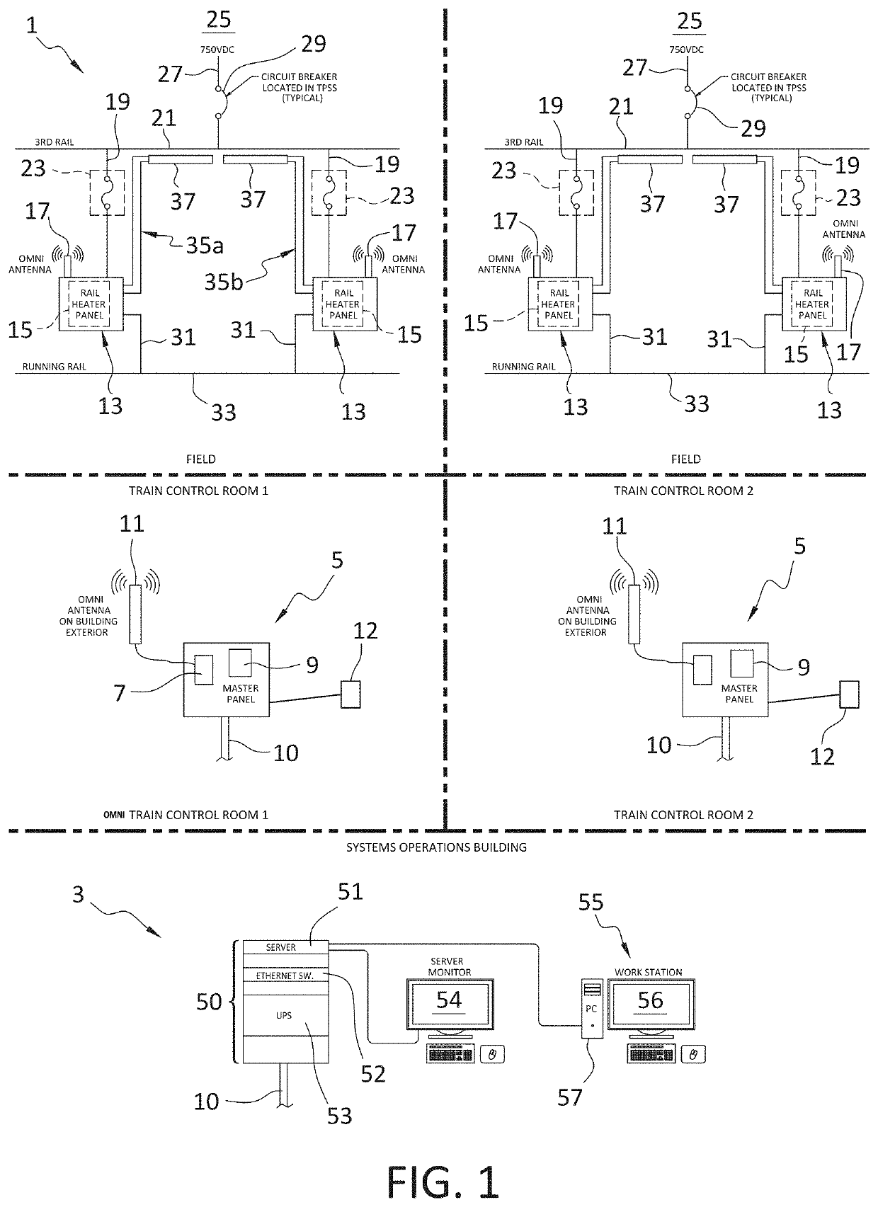
[0030]With reference to FIG. 1, the third rail heater control system 1 of the invention generally comprises a master control station 3 remotely located from the railway stations, a plurality of local relay units 5 located in the railway stations (which together form the digital controller of the system), and a plurality of trackside junction boxes 13.

[0031]The local relay units 5 each include a transceiver 7 connected to a programmable logic circuit (PLC) 9. The local relay units 5 are optically coupled to the master control station 3 via an optical cable 10, and are radio linked the relatively short distances to the junction boxes 13 via an antenna 11 connected to the output of the transceiver 7. Such an architecture advantageously obviates the need to install a communications cable in the relatively harsh trackside environment where the junction boxes 13 are mounted, while keeping the length of the radio link short, thereby minimizing the chance that the radio link will be degrade...


PUM


Abstract

A system for remotely controlling third rail ribbon heaters is provided for preventing the accumulation of ice and snow on the rails. The system includes a plurality of switching assemblies that control a flow of electric current from the third rail of a railway to ribbon heaters mounted on the third rail. A remotely located digital controller provides switching commands to the switching assemblies via a radio link. The switching assemblies include current and voltage sensors that continuously provide current and voltage information that allows the digital controller to accurately predict when a heater failure condition is likely to occur so that ribbon heaters may be preemptively and safely replaced before failure. Each of the switching assemblies is contained in a junction box that includes both a door panel and a safety switch that disconnects the switching assembly from third rail current when the door panel is opened for improved safety.

Description

FIELD OF THE INVENTION[0001]This invention relates to systems for controlling the electrical-resistance heaters used to prevent the formation of ice on the third rail of electrically-powered railways.BACKGROUND OF THE INVENTION[0002]Third rail heater systems are generally known in the prior art. The purpose of such heaters is to prevent the accumulation of ice on the third rail of an electrically-powered railway that would otherwise interfere with electrical contact between the contact plate of an electrically-powered train car and the 750 volt DC current that is conducted through the third rail.[0003]In such systems, long strip-like electrical resistance heaters (known as “ribbon heaters” or “heat tape” in the art) are mounted flush along the outer side of the central flange of the “I”-shaped cross-section of the third rail. Each of the ribbon heaters is electrically connected to the third rail so as to be powered by the 750 volts DC that such rails conduct. Current flow to the rib...

Claims


Application Information

Patent Timeline
Patent Type & Authority Applications(United States)
IPC IPC(8): E01H8/08E01B19/00E01B7/24E01B7/20
CPCE01B7/20E01H8/08E01B7/24E01B19/00B60M1/30B60M3/00Y02A30/30
Inventor KROHN, WALTER
Owner M C DEAN IP LLC
Why Eureka
Try Eureka