Flexible and foldable electromagnetic shielding

a technology of electromagnetic shielding and flexible materials, applied in the field of flexible electromagnetic shielding, can solve the problems of difficult to provide flexible em shielding, and difficult to meet the requirements of civilian or military enclosures, and achieve the effect of high effectiveness

Active Publication Date: 2020-10-01
WARWICK MILLS INC
View PDF0 Cites 5 Cited by
  • Summary
  • Abstract
  • Description
  • Claims
  • Application Information

AI Technical Summary

Benefits of technology

[0047]Attachment of the EM shielding laminate to surrounding structures can be by lanyards and/or webbing. In embodiments, a lanyard and/or webbing penetrates the laminate sheet and is attached to a rear surface thereof, and a conductive patch is installed on the rear surface over the lanyard and/or webbing so as to block any EM emissions that might otherwise leak through the penetration(s). Instead of, or in addition to, a conductive patch, the lanyard and/or webbing can be covered by a layer of an elasto...

Problems solved by technology

However, when protecting mobile assets, it is often necessary for camouflage to be “soft packable,” such that it can be collapsed or folded into a compact space for transportation, and then unpacked and deployed when a destination is reached.
Unfortunately, it can be difficult to provide EM shielding that is both flexible and foldable for applications that require EM shielding over a broad range of frequencies.
For this reason, flexible, “soft packable” lightweight EM shielding is not generally available for civilian or military enclosures.
Suppressing EM radiation by 20-80 dB over the SHF range can be challenging for a soft packable system.
Suppression by at least 20 dB over the full range of frequencies from LF to SHF is difficult in all cases, and is even more difficult for a soft packable system.
This is because a continuous, flexible conductive layer that is thick enough to block low frequency EM radiation is likely to suffer metal fatigue and develop cracks after repeated flexing and folding.
Such cracks can widen over time and permit leakage of higher frequency EM radiation through the shielding.
For example,...

Method used


Image

  • Flexible and foldable electromagnetic shielding
  • Flexible and foldable electromagnetic shielding
  • Flexible and foldable electromagnetic shielding

Examples


example b

, FIG. 3D

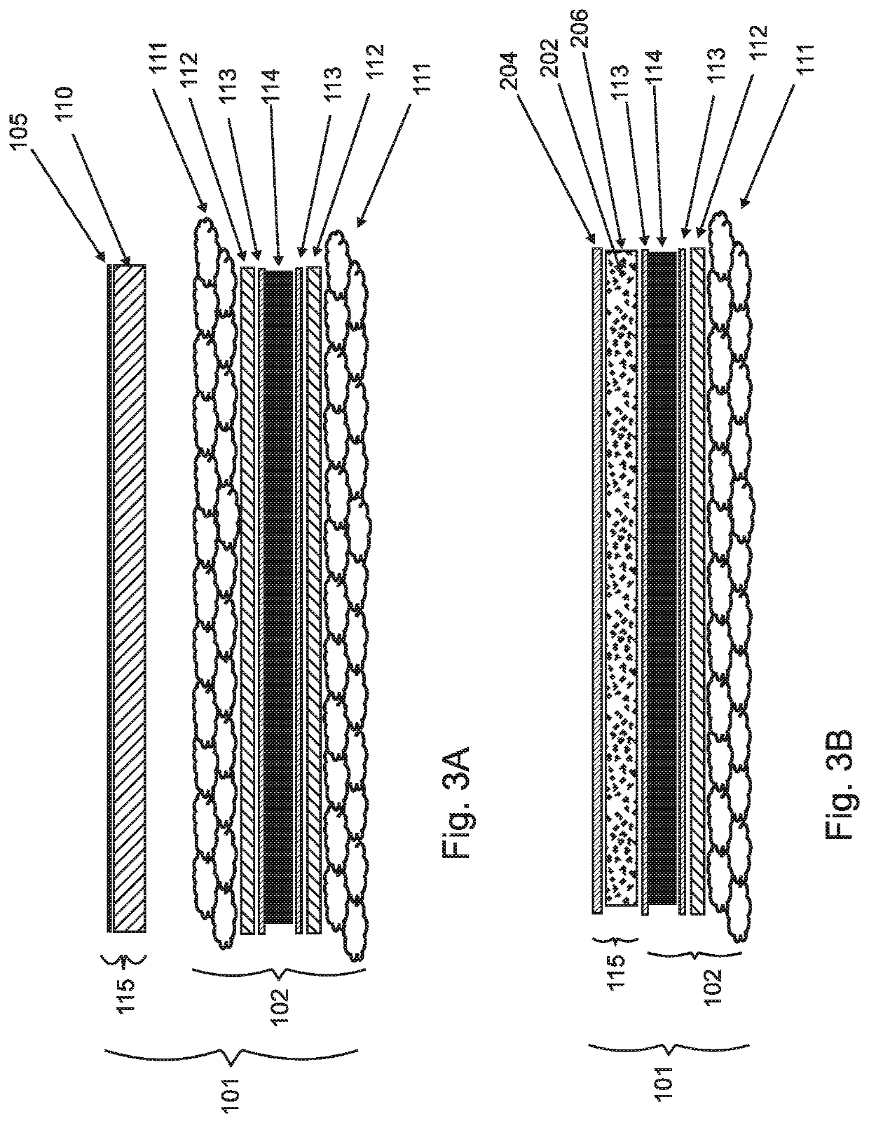
[0123]Crosslinked polyether urethane topcoat 204[0124]Polyester urethane absorbing tie coat adhesive layer 206 filled with 5-25% by dry weight of Ferrite and carbon black 202[0125]Moisture resistant phenolic primer 113[0126]CVD deposited aluminum 114[0127]PET film 110[0128]Moisture resistant phenolic primer 113[0129]Polyester urethane adhesive tie coat layer 112[0130]Isocyanate primer 113[0131]Support Textile 111[0132]Isocyanate primer 113[0133]Polyester urethane adhesive tie coat layer 112[0134]Moisture resistant phenolic primer 113[0135]CVD deposited aluminum 114[0136]PET film 110[0137]Moisture resistant phenolic primer 113[0138]Crosslinked polyether urethane topcoat 204

[0139]Note that Example B includes two LF layers, each of which includes a CVD deposited LF aluminum layer 114 applied to an underlying PET film layer 110. Note further that all of Examples B-E include “topcoat” layers 204 on both outward facing sides of the EM shield laminate. The topcoat layers 204 can c...

example c

, FIG. 3E

[0140]Crosslinked polyether urethane topcoat 204[0141]Polyester urethane absorbing tie coat adhesive layer 206 filled with 5% to 25% by dry weight of Ferrite and carbon black 202[0142]Moisture resistant phenolic primer 113[0143]0.0005″ aluminum foil 114[0144]Moisture resistant phenolic primer 113[0145]Polyester urethane adhesive tie coat layer 112[0146]Isocyanate primer 113[0147]Support Textile 111[0148]Isocyanate primer 113[0149]Polyester urethane absorbing tie coat adhesive layer 206 filled with conductive carbon black loading at 5% to 25% of dry film 202[0150]Crosslinked polyether urethane topcoat 204

[0151]Note that Example C includes two HF barriers 115 formed as polyester urethane tie coat adhesives 206 that are filled with conductive and ferrous particles 202. The particles 202 can be in a resin binder, and can include carbon black, conductive carbon black, graphite powder, Fe3O4 and other iron oxides, and / or ferrite particles including spherical materials. The HF bar...

example d

, FIG. 3F

[0152]Crosslinked polyether urethane topcoat 204[0153]Polyester urethane absorbing tie coat adhesive layer 206 filled with 5% to 25% by dry weight of Ferrite and carbon black 202[0154]Polyester urethane adhesive tie coat layer 112[0155]Moisture resistant phenolic primer 113[0156]support textile 1 oz / yd 111 with silver plated layer 114[0157]Moisture resistant phenolic primer 113[0158]Polyester urethane absorbing tie coat adhesive layer 206 filled with conductive carbon black loading at 5% to 25% of dry film 202[0159]Crosslinked polyether urethane topcoat 204


PUM

PropertyMeasurementUnit
Fractionaaaaaaaaaa
Fractionaaaaaaaaaa
Fractionaaaaaaaaaa

Abstract

A flexible, foldable EM barrier attenuates electromagnetic radiation by at least 20 dB from 1 GHz to 30 GHz. The barrier comprises an LF layer that blocks EM radiation at least at low frequencies, laminated to a textile support layer that reduces stress cracking of the LF layer and prevents widening of any cracks that do form. Embodiments further comprise an HF layer that blocks EM radiation at high frequencies, such as a metallized polymer film and/or an elastomer layer filled with conductive particles. The LF layer can be foil, mesh, or electroless metallization of the support textile or of another textile. A thermal insulation layer can be included. A topcoat can block UV, and primer layers can resist moisture. Barriers can be joined to each other and/or to adjacent structures by lanyards, webbing, sewing, soft connections, and/or flex joints formed by adhesively attached metallized textiles or films.

Description

RELATED APPLICATIONS[0001]This application claims the benefit of U.S. Provisional Application No. 62 / 824,444, filed on Mar. 27, 2019, which is herein incorporated by reference in its entirety for all purposes.FIELD OF THE INVENTION[0002]The invention relates to electromagnet shielding, and more particularly to flexible electromagnetic shielding.BACKGROUND OF THE INVENTION[0003]Camouflage, which can be broadly defined as apparatus and methods for protecting covert mobile and stationary objects from detection, is an important requirement for many civilian and military applications. There are at least two principle requirements that must be met by camouflage so as to avoid detection. First, a camouflage shield must mimic the energy reflective properties of a surrounding environment. To this end, camouflage that is used to shield vehicles and other mobile and stationary ground-based assets typically presents colors and marking patterns that attempt to match colors and patterns in the vi...

Claims


Application Information

Patent Timeline
IPC IPC(8): H05K9/00D06M11/83
CPCH05K9/0084H05K9/009D06M11/83H05K9/0088D06N3/14D06N3/0063D06N2209/048B32B33/00B32B2255/10B32B7/12B32B2255/02B32B2307/202B32B2307/54B32B2262/0246B32B2262/0261B32B2307/304B32B2307/732B32B2255/205B32B2307/212B32B2262/0276B32B27/36B32B2262/04B32B2262/0269B32B15/20B32B27/12B32B15/14B32B2262/0253B32B2571/00B32B2262/062
Inventor HOWLAND, CHARLES A
Owner WARWICK MILLS INC
Why Eureka
Try Eureka