Water injection into a hydrocarbon reservoir
- Summary
- Abstract
- Description
- Claims
- Application Information
AI Technical Summary
Benefits of technology
Problems solved by technology
Method used
Image


Examples
examples 1-8
, Including Comparative Examples 1-5
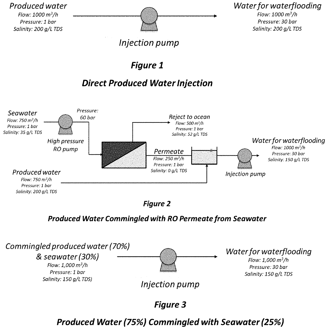
[0072]Each of these examples is a theoretical calculation of the power requirements for the individual pumps and the total power required (see Tables 1 and 2). The power requirements were calculated based on the following assumptions:
Waterflooding flow required: 1,000 m3 / h
Injection pressure needed: Examples 1-7: 30 bar (3 MPa); Example 8: 60 bar (6 MPa)
PRO pressure: Examples 6 & 8: 30 bar (3 MPa); Example 7: 3 bar (0.3 MPa)
PW salinity: 200 g / L (20%) total dissolved solids (TDS)
Seawater TDS: 35 g / L
[0073]Seawater RO operating pressure: 60 bar (6 MPa)
Seawater RO recovery: 33%
Nanofilter operating pressure: 20 bar (2 MPa)
Nanofilter recovery: 67%
Temperature: 25° C.
[0074]Pump efficiency: 75%
Produced water dilution by PRO permeate: 25%
[0075]For Example 8, the energy benefit is not directly comparable since the required injection pressure is assumed to be 60 bar (60 MPa).
[0076]The following pumping energy equation was used to derive these results:
Ph(kW)=qρ...
example 6
[0089]This Example (see FIG. 6) also assumes the same requirements as the comparative examples in terms of pressure and flow rate of injected water. A high pressure pump conveys PW with a salinity of 200 g / L TDS at 30 bar (3 MPa) and a flow rate of 750 m3 / h to a pressure retarded osmosis (PRO) unit as the “draw” stream. Another low pressure pump conveys seawater (salinity 35 g / l TDS) at 3 bar (0.3 MPa) and a flow rate of 750 m3 / h to the PRO unit as the “feed” stream.
[0090]Because the osmotic pressure differential exceeds the hydrostatic head differential, pure water is drawn across the PRO membrane against the static pressure head from the seawater stream to the PW stream. At the assumed permeate recovery rate of 33%, the permeate flow is 250 m3 / h. The permeate flow combined with the original PW flow is now 1000 m3 / h and the pressure remains at 30 bar (3 MPa). Through the addition of the permeate, the salinity of the PW has been reduced by 25% from 200 g / L to 150 g / L TDS. This flow ...
example 7
[0091]In the event that the required injection pressure is higher than the limit for commercially available PRO membranes, or simply because the existing equipment arrangement favours having the PRO unit upstream, it may be desirable to have the high-pressure pump located after the PRO unit. FIG. 7 shows an example of this arrangement. Low pressure pumps convey 750 m3 / h of both PW and seawater streams each at 3 bar (0.3 MPa) to the PRO unit. Although the term “pressure retarded osmosis” is used, in fact there is a negligible pressure increase across the membrane in this example and the process is more accurately referred to as “osmotic dilution” of the produced water. The 30 bar (3 MPa) injection pressure can be higher or lower but is used in this example to provide an effective method for comparing the various configurations. Although energy savings are not realized, the key benefits of i) more water available for waterflooding, ii) lower salinity and iii) less reservoir incompatib...
PUM
 Abstract
Description
Claims
Application Information
 - R&D
- Intellectual Property
- Life Sciences
- Materials
- Tech Scout
- Unparalleled Data Quality
- Higher Quality Content
- 60% Fewer Hallucinations
Browse by: Latest US Patents, China's latest patents, Technical Efficacy Thesaurus, Application Domain, Technology Topic, Popular Technical Reports.
© 2025 PatSnap. All rights reserved.Legal|Privacy policy|Modern Slavery Act Transparency Statement|Sitemap|About US| Contact US: help@patsnap.com