
Preparation of therapeutic foam

a technology of foam and foam injection, which is applied in the field of preparation of therapeutic foam, can solve the problems of affecting the quality of the foam, the difficulty of a physician wishing to fill the syringe exclusively with a gas other than air, and the potential danger of injecting air into the body. , to achieve the effect of simple operation, good quality and less cos

Active Publication Date: 2021-01-07
BOSTON SCI MEDICAL DEVICE LTD
View PDF0 Cites 1 Cited by
  • Summary
  • Abstract
  • Description
  • Claims
  • Application Information

AI Technical Summary

Benefits of technology

The solution ensures the production of consistent, sterile clinical foam with the correct gas composition, reducing the risk of air bubbles and improving the safety and efficacy of treatments by using gases that are more readily absorbed by the body.

Problems solved by technology

A problem with foamed clinical preparations is the production of a consistent, sterile product for use by a physician.
A further issue is the potential danger of injecting quantities of air into the body, since nitrogen is highly insoluble.
Extemporaneously prepared foams made with air are widely used, but work conducted by the inventors has shown that even the smallest volumes of nitrogen, of the order of a few percent, give rise to bubbles which endure in the vascular system and are potentially harmful.
However, there are difficulties for a physician wishing to fill a syringe exclusively with a gas other than air.
The most straightforward method would be to connect the nozzle of the syringe to a line from a cylinder of the desired gas, but it is difficult reliably to exclude all air / nitrogen and virtually impossible to check the purity of the gas component in the syringe.
However, this involves a large amount of gas being provided to fill the fume cupboard when only a very small amount of gas is necessary to fill the syringe.
Furthermore, it is still difficult to be confident that the contents of the fume cupboard, and therefore the gas in the filled syringe, are exclusively the desired gas or gas mix.

Method used


Image

  • Preparation of therapeutic foam
  • Preparation of therapeutic foam
  • Preparation of therapeutic foam

Examples


first embodiment

[0072]1% polidocanol solution is used in the first embodiment, but it will be appreciated by those of ordinary skill in this art that there are a number of sclerosing agents which is perform well in the treatment of varicose veins. The most common alternative to polidocanol is sodium tetradecyl sulphate.

[0073]In further modifications of the first embodiment, the carbon dioxide gas could be replaced with another appropriate gas which is dissolved in or absorbed by blood or is harmlessly absorbed by the body in some other way. Examples include oxygen, nitrous oxide, helium, neon, xenon. Carbon dioxide, oxygen or a mixture of the two are preferred. Oxygen, although not very soluble, is taken up rapidly by haemoglobin in venous blood and is therefore suitable for use in a foam for injection into varicose veins. Because of its insolubility in water, foams made with oxygen last longer than foams made with carbon dioxide and it is easier to make a fine bubble microfoam with oxygen or anoth...

second embodiment

[0080]The second embodiment is designed to be used with a “double piston” type syringe which will be described below. Once such a syringe is charged with gas and liquid, a second plunger in the syringe is oscillated to make foam; all that is required is that the nozzle of the syringe be sealed.

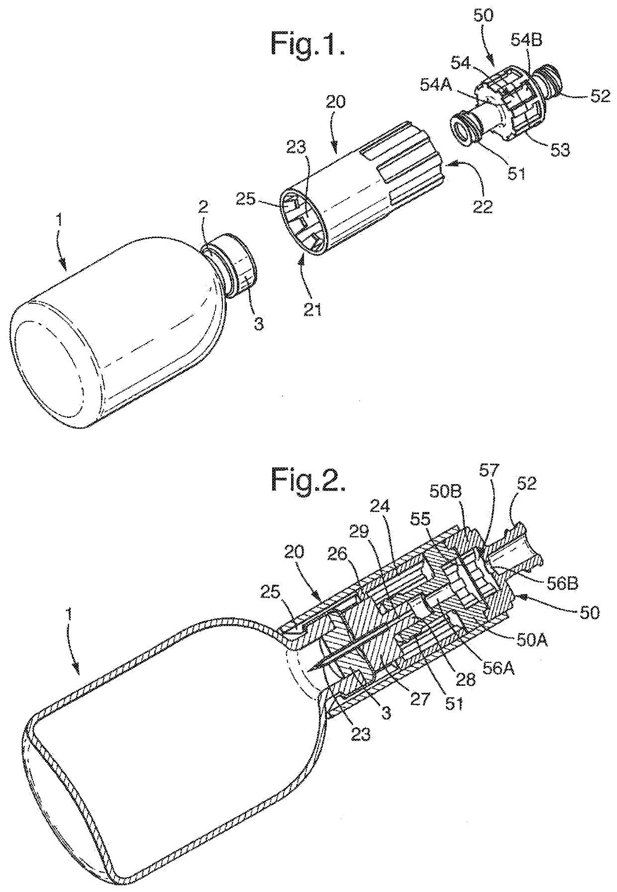
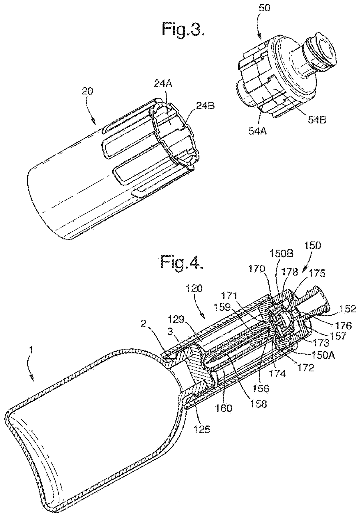
[0081]A vial 1 is provided having exactly the same features as that of the first embodiment. A transfer device 120 is shown mounted on the vial. The transfer device is of overall cylindrical shape and is attached to the vial 1 by means of barbed attachment formations 125 which engage the neck region 2 of the vial 1, as for the first embodiment. The reminder of the transfer device, however, is different from the first embodiment and comprises simply a series of axial grooves 129 in the interior wall.

[0082]A syringe connector device 150 is received in the transfer device 120. The syringe connector device 150 is formed with axial lands (not shown) complementary to the grooves 129 of the transfer ...

fifth embodiment

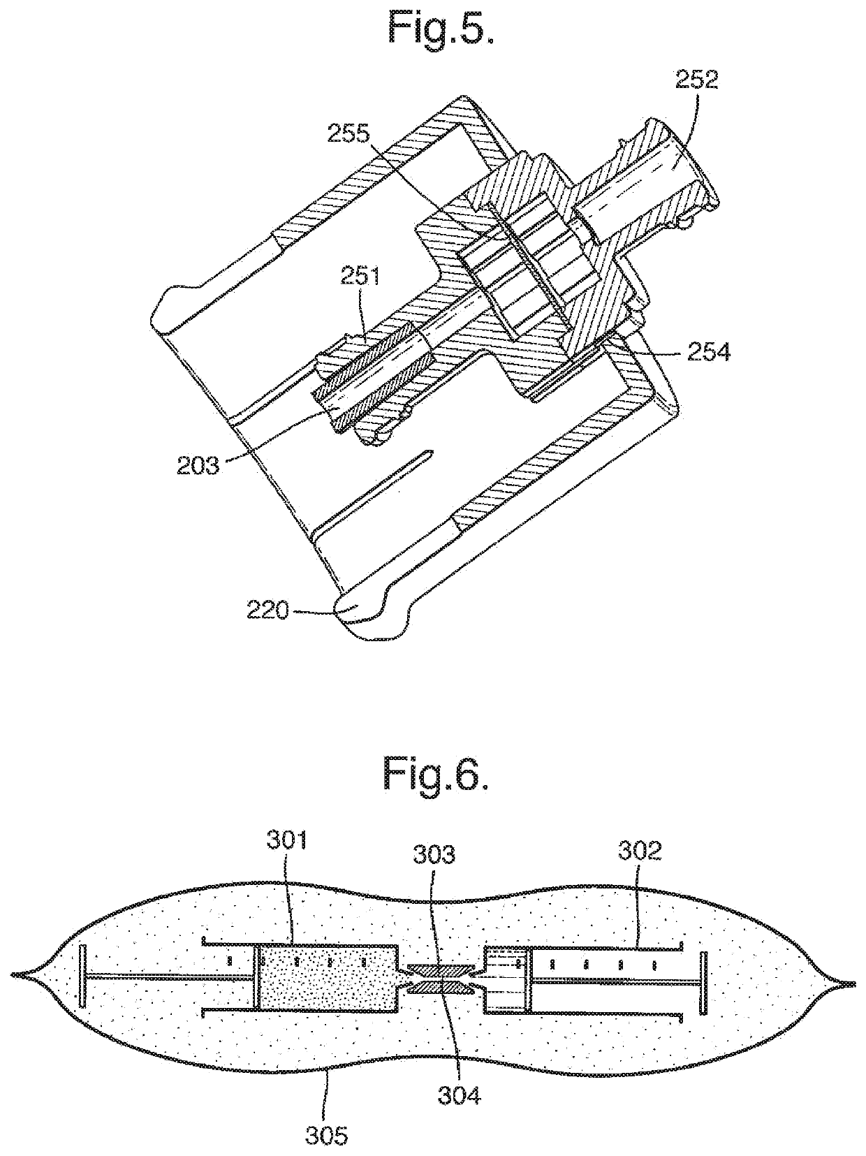
[0098]the invention is illustrated schematically in FIG. 6. Two 20 ml syringes 301, 302 are supplied, connected together by means of a standard syringe connector 303 having a bore 304 of cross section approximately 1 mm. The first syringe 301 contains 8 ml of substantially pure carbon dioxide whilst the second contains 2 ml of 1% polidocanol solution. The syringes are enclosed in a pouch 305 of metallised plastics laminate, in an atmosphere of substantially pure carbon dioxide at a pressure of 1.1 bar absolute (i.e. 0.1 bar over atmospheric).

[0099]To use the fifth embodiment, the user simply breaks open the package and pumps the syringes to produce foam (either manually or using a machine as described above).

[0100]In a modified version of the fifth embodiment, the twin syringes are replaced with a double plunger syringe of the type described above, charged with the same quantities of carbon dioxide and 1% polidocanol solution.

[0101]The syringes are pre-filled with appropriate volume...


PUM

PropertyMeasurementUnit
thicknessaaaaaaaaaa
thicknessaaaaaaaaaa
pressureaaaaaaaaaa

Abstract

A device is described for facilitating the preparation of therapeutic foam e.g. for the treatment of varicose veins. A pressurised vial contains a sclerosant liquid, e.g., polidocanol solution, and a sterile gas which is readily absorbed by the body, e.g., carbon dioxide, oxygen or a mixture of these gases. The vial is provided either with a specialised stopper / seal into which a syringe nozzle may be inserted or alternatively a septum seal which may be penetrated by a hypodermic needle. The quantities of gas and liquid and the pressure in the vial are pre-set so that, on connection of a syringe to the vial, a predetermined volume of both gas and liquid is transferred to the syringe, with the intention that the syringe is then used to make a foam by known means. The use of the vial ensures that the ratio of gas to liquid in the foam is standardised, and also provides a convenient way of packaging the gas and liquid and of filling the syringe in a sterile manner.

Description

CROSS-REFERENCE TO RELATED APPLICATIONS[0001]This application is a continuation of U.S. patent application Ser. No. 14 / 470,102, filed Aug. 27, 2014, now U.S. Pat. No. 10,773,864, which is a continuation of U.S. patent application Ser. No. 12 / 801,645, filed Jun. 18, 2010, abandoned, which is a continuation of U.S. patent application Ser. No. 11 / 919,749, filed Jan. 25, 2008, abandoned, which is a national stage filing under 35 U.S.C. § 371 of International Application No. PCT / GB2006 / 0017744, filed on May 12, 2006, which claims the benefit of priority to British Patent Application No. 0509845.4, filed May 13, 2005, the entire contents of each of which are hereby incorporated by reference.BACKGROUND OF THE INVENTION[0002]The present invention relates to apparatus and a method for dispensing predetermined quantities of liquid and gas into a syringe or similar device and also to a pack containing a syringe or other vessel charged with liquid and gas. The invention relates especially to sy...

Claims


Application Information

Patent Timeline
Patent Type & Authority Applications(United States)
IPC IPC(8): B65D47/06A61J1/14B65D51/00A61J1/20B65D83/14A61K9/12A61K31/08A61J1/00B01F25/46
CPCB65D47/06A61J1/1437B65D51/002A61J1/1406A61J1/2096A61J1/2037A61K9/122A61K31/08A61J1/2086A61J1/201B65D83/756
Inventor HARMAN, ANTHONY DAVIDMIJERS, JAN WILLEM MARINUSROBINSON, NIKKI
Owner BOSTON SCI MEDICAL DEVICE LTD
Learn More